Do you have a question about the Fujitsu AOYG12KMTA and is the answer not in the manual?
Details compressor type, refrigerant type, precharged refrigerant amount, and pipe length specifications.
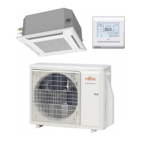
Illustrates the refrigerant flow path for specific indoor/outdoor unit model combinations.
Illustrates the refrigerant flow path for the ASYG12/AOYG12 model combination.
Illustrates the refrigerant flow path for the ASYG14/AOYG14 model combination.
Shows the electrical circuit connections for the outdoor unit components.
Shows the electrical circuit connections for the indoor unit components.
Details the PCB layout and connections for the indoor unit.
Details the PCB layout and connections for the outdoor unit.
Lists error codes and corresponding blinking patterns for indoor unit operation and timer lamps.
Core refrigeration cycle components for the 14 model: compressor, valves, solenoids.
Explains how the compressor frequency is controlled based on room and outdoor temperatures.
Describes compressor frequency control in heating mode based on room temperature.
Describes outdoor fan speed control based on compressor frequency and outdoor temperature.
Explains compressor frequency ranges, startup control, and limitations by outdoor temperature.
Describes ON/OFF timer, program timer, and sleep timer functions for wireless remote control.
Provides procedures for performing test operations using wired or wireless remote controllers.
Explains conditions for starting and completing defrost operations.
Details protection controls like discharge gas temperature overrise and current release.
Lists error contents, indoor unit display patterns, and wired remote controller error codes.
Explains self-diagnosis and error code history display for wired remote controllers.
Provides diagnostic steps for various error codes encountered with the unit.
Guides on troubleshooting issues without specific error codes, like no power or no cooling/heating.
Diagnostic methods and replacement procedures for the compressor.
| Type | Air conditioner outdoor unit |
|---|---|
| Multi-split | No |
| Product color | White |
| Gas hose diameter | 9.5 mm |
| Hose length (max) | 15 m |
| Inverter technology | Yes |
| Liquid hose diameter | 6.35 mm |
| Refrigerating medium | R32 |
| Air conditioner functions | Cooling, Heating |
| Refrigerating medium weight | 700 g |
| Cooling capacity in watts (nominal) | - W |
| Operating temperature (cooling) (T-T) | -10 - 46 °C |
| Operating temperature (heating) (T-T) | -15 - 24 °C |
| Seasonal efficiency rating (cooling) (SEER) | - |
| AC input voltage | 230 V |
| Current (cooling) | 6.5 A |
| Current (heating) | 9 A |
| AC input frequency | 50 Hz |
| Design load (cooling) | - kW |
| Hourly energy consumption (cooling) | - kWh |
| Indoor unit noise level (high speed) | - dB |
| Outdoor unit depth | 290 mm |
| Outdoor unit width | 663 mm |
| Outdoor unit height | 541 mm |
| Outdoor unit weight | 25000 g |
| Outdoor units quantity | 1 |
| Outdoor unit noise level | 58 dB |
| Cooling airflow (outdoor unit) | 770 m³/h |
| Outdoor unit sound power level | 50 dB |