En-8
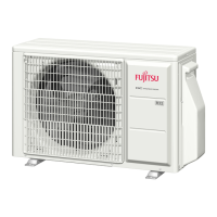
(5) While pulling the control box towards you, remove in the right direction.
• Do not remove the thermistor.
• Do not damage the terminals on the removed wires. (See the figure below)
Thermistor
Control box
Terminals
Control box
(5)
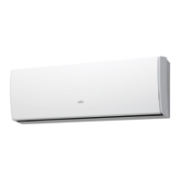
13.3.3. Installing communication box
(1) Install the communication box on the main unit and secure it with the provided
screw at the location shown below.
View A (Detail view)
Screw
Motor cover
View A (Detail view)
(2) Use the hole on the motor cover and secure the wire from the communication box
with the provided binder.
(See the figure below)
Binder
Cut away the tip of
the binder.
Hole
13.3.4. Installing control box
(1) Set the control box toward the bottom so that it touches the motor cover from the
right.
Insert the protruding part of the main
unit on the fi xture (1 location) into
the control box.
Control box
• The installation method of the control box is different for each destination country.
(See figure below)
(When installing, reuse the screw that was removed in 13.3.2. Removing control
box.)
(2) Secure the control box with a screw. (Use a long screw.)
(3)
(2)
(3) Fasten the earth wires of the heat exchanger together as shown in the left figure
above. (Use a short screw here.)
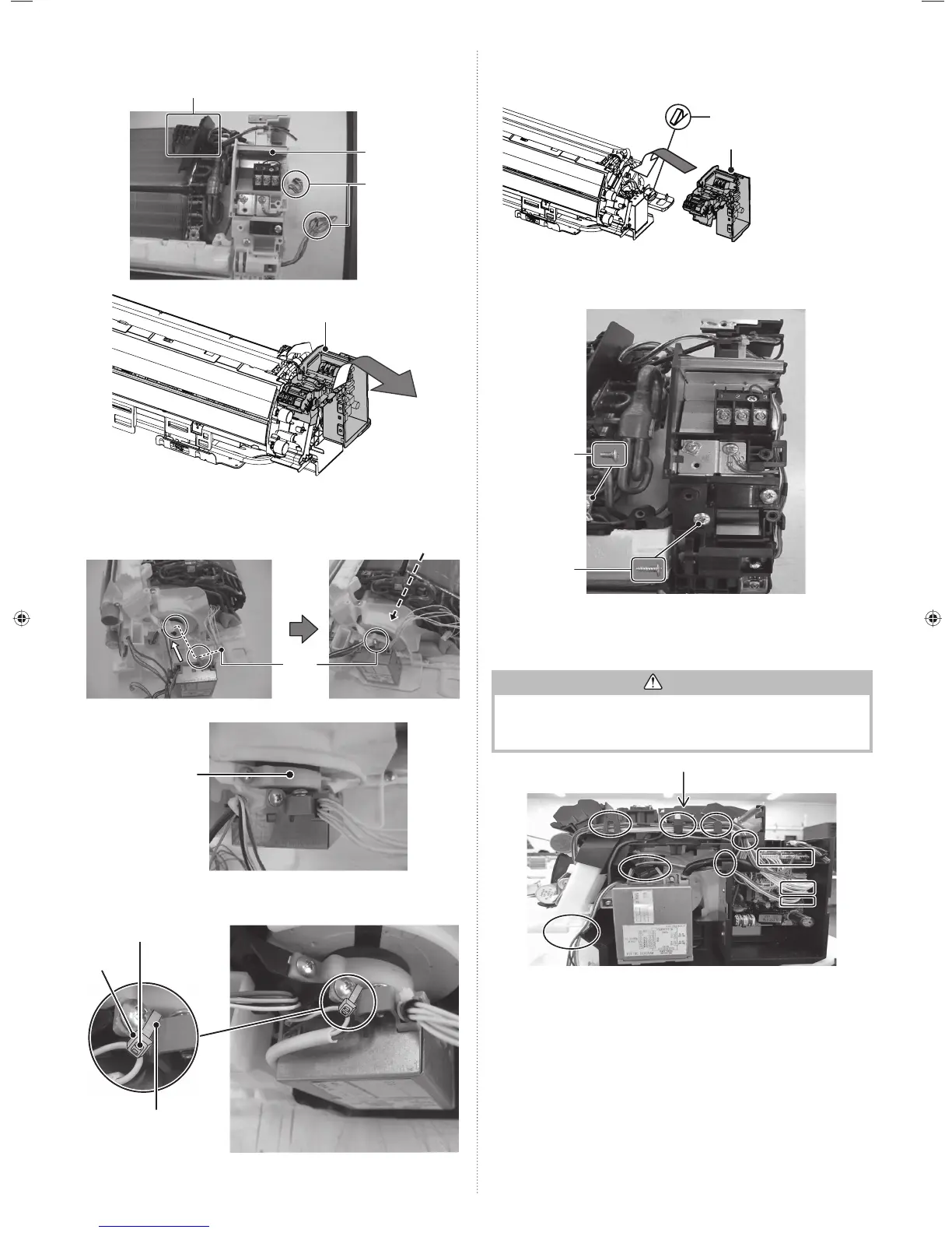
(4) Hitch the wires onto the fixtures as shown in the oval circles below. Then connect
the connectors in the squares to the terminals respectively.
(Each terminal should form a pair with a connector.)
CAUTION
• Ensure that the connector is properly inserted.
Otherwise, it may result in erroneous operation.
• Be careful not to damage the parts on the board.Otherwise,
it will cause malfunction.
(4)
(5) Fasten the earth wire (green) in the communication box together with the earth
wire (green) on the board of the control box as shown below and in the bottommost
figure of the previous page.
9333005072_IM.indb 89333005072_IM.indb 8 2013-9-24 11:45:102013-9-24 11:45:10
 Loading...