En-12
9.2.1. Setting for low noise mode
(1) Switch to “Local setting mode” by pressing [MODE] button (SW1) for 3 seconds or
more.
(2) Conrm (POWER / MODE) blinks 9 times, and press [ENTER] button (SW3).
POWER
ERROR
PUMP
DOWN
LOW
NOISE
PEAK
CUT
MODE (L1) (L2) (L3) (L4) (L5) (L6)
Blink
(9 times)
○ ○ ○ ○ ○ ○ ○
Sign “
○
”: Lights off, “
●
”: Lights on, () : Number of blinking
(3) Press [SELECT] button (SW2), and adjust LED display as shown below. (Current
setting is displayed)
LOW
NOISE
(L2) (L3)
LOW NOISE
MODE
○ Blink
Sign “
○
”: Lights off
(4) Press [ENTER] button (SW3).
LOW
NOISE
(L2) (L3)
LOW NOISE
MODE
○ ●
Sign “
○
”: Lights off, “
●
”: Lights on
(5) Press [SELECT] button (SW2), and adjust LED lamp as shown in below gure.
PEAK
CUT
(L4) (L5) (L6)
Level 1
○ ○
Blink
Level 2
○
Blink
○
Sign “
○
”: Lights off
The noise of Level 2 is lower than the one of Level 1.
(6) Press [ENTER] button (SW3) and x it.
PEAK
CUT
(L4) (L5) (L6)
Level 1
○ ○
●
Level 2
○
●
○
Sign “
○
”: Lights off, “
●
”: Lights on
(7) Return to “Operating status display (Normal operation)” by pressing [EXIT] button
(SW4).
In case of missing how many times [SELECT] and [ENTER] • button are pressed,
restart from the beginning of operation procedure after returning to “Operation status
display (normal operation)” by pressing the [EXIT] button once.
9.2.2. Setting for peak cut mode
(1) Switch to “Local setting mode” by pressing [MODE] button (SW1) for 3 seconds or
more.
(2) Conrm (POWER / MODE) blinks 9 times, and press [ENTER] button (SW3).
POWER
ERROR
PUMP
DOWN
LOW
NOISE
PEAK
CUT
MODE (L1) (L2) (L3) (L4) (L5) (L6)
Blink
(9 times)
○ ○ ○ ○ ○ ○ ○
Sign “
○
”: Lights off, “
●
”: Lights on, () : Number of blinking
(3) Press [SELECT] button (SW2), and adjust LED lamp as shown below. (Current
setting is displayed)
LOW
NOISE
(L2) (L3)
PEAK CUT
MODE
Blink
○
Sign “
○
”: Lights off
(4) Press [ENTER] button (SW3).
LOW
NOISE
(L2) (L3)
PEAK CUT
MODE
● ○
Sign “
○
”: Lights off, “
●
”: Lights on
(5) Press [SELECT] button (SW2), and adjust LED lamp as shown in below gure.
PEAK
CUT
(L4) (L5) (L6)
Level 1 0% of rated input ratio
○ ○ Blink
Level 2 50% of rated input ratio
○ Blink ○
Level 3 75% of rated input ratio
○ Blink Blink
Level 4 100% of rated input ratio
Blink
○ ○
Sign “
○
”: Lights off
(6) Press [ENTER] button (SW3) and x it.
PEAK
CUT
(L4) (L5) (L6)
Level 1 0% of rated input ratio
○ ○ ●
Level 2 50% of rated input ratio
○ ● ○
Level 3 75% of rated input ratio
○ ● ●
Level 4 100% of rated input ratio
● ○ ○
Sign “
○
”: Lights off, “
●
”: Lights on
(7) Return to “Operating status display (Normal operation)” by pressing [EXIT] button
(SW4).
When pressed number is lost during operation, restart from the beginning of operation •
procedure after returning to “Operation status display (normal operation)” by pressing
the [EXIT] button once.
10. EXTERNAL INPUT AND OUTPUT
10.1. External input
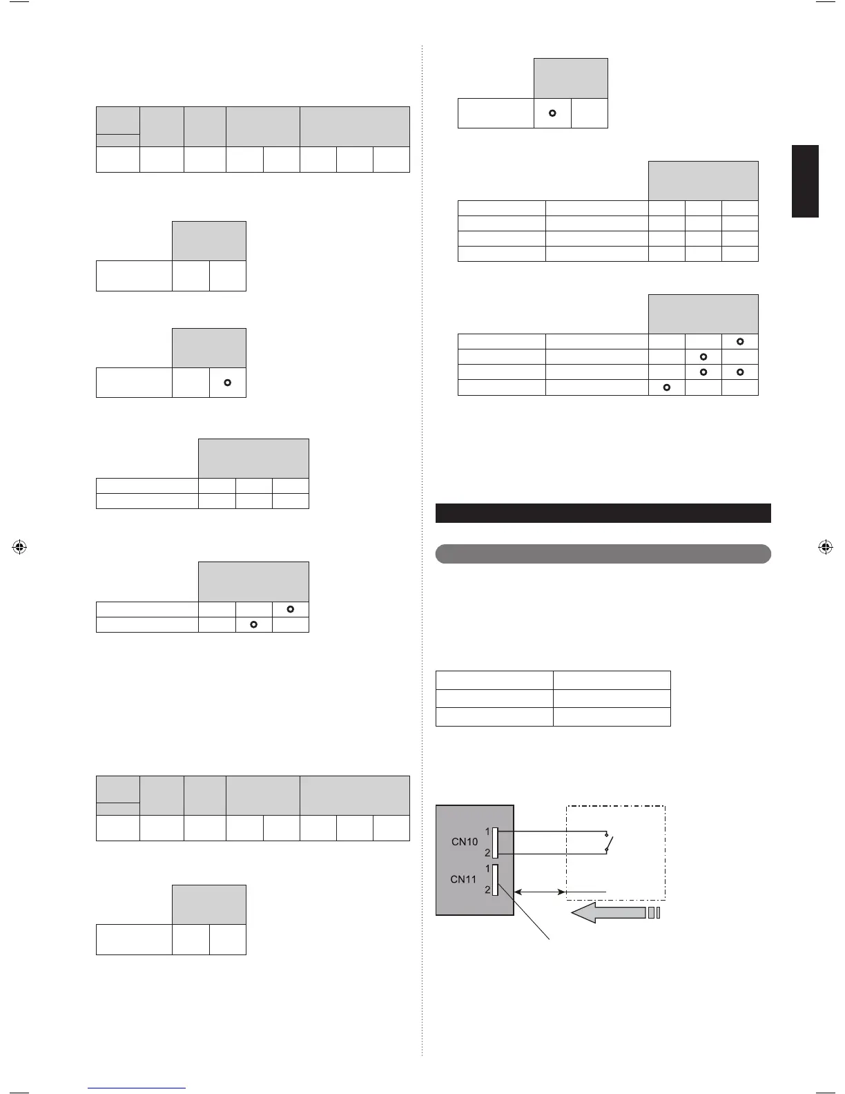
10.1.1. Wiring of connector
ON/OFF of the “Low noise mode”, and “Peak cut mode” functions can be enabled with an
external eld device.
When installing connection cable, specied part (optional parts) must be used.
Refer to section 9.2. Table. Settings List, for the required function. The function must be
set for the external input to work.
Input Connector
Low noise mode CN10
Peak cut mode CN11
* Make the distance from the PC board to the connected unit within 10m (33ft).
• Contact capacity : 24VDC or more, 10mA or more.
Circuit diagram example
Outdoor unit control
PC board
Connected unit (Field
supply)
Ex.) Switch
Connection cable (option)
Signal
Connector
*10m (33ft)
 Loading...