Do you have a question about the Fujitsu ARHC72LHTA and is the answer not in the manual?
Details electrical parameters like capacity, power, current, and efficiency.
Provides sound pressure levels for indoor and outdoor units.
Covers compressor type, refrigerant used, and charge quantities.
Lists technical details for fan motors.
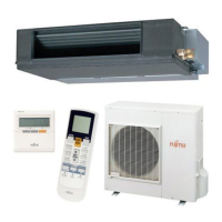
Lists overall dimensions and weights for indoor and outdoor units.
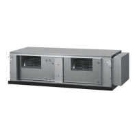
Displays various views with detailed dimensions for the ARHC72LHTA indoor unit.
Indicates the inside and outside diameters of the drain pipe.
Presents detailed views and dimensions for the ARHC90LHTA indoor unit.
Specifies the drain pipe diameter for the ARHC90LHTA unit.
Shows top, front, rear, and side views with detailed dimensions for the outdoor unit.
Illustrates the refrigerant flow path and components for both units.
Lists and explains the various thermistors used in the system.
Details the electrical connections and components for the outdoor unit.
Shows the electrical connections and components for the indoor unit.
Diagrams the control unit and its main PCBs (Control, Power Supply, Filter).
Provides a detailed schematic of the main printed circuit board.
Shows the schematic for the indoor unit's power supply PCB.
Presents the schematic for the indoor unit's filter PCB.
Diagrams the inverter assembly and main PCBs for the outdoor unit.
Details the transistor PCB schematic for the outdoor unit.
Shows a detailed schematic of the second main PCB for the outdoor unit.
Details schematics for various components like thermistors and switches.
Presents the schematic for the main filter PCB of the outdoor unit.
Shows the schematic for the inverter filter PCB of the outdoor unit.
Lists error codes and their descriptions for troubleshooting.
Explains LED indicators and error codes for the outdoor unit.
Identifies parts like Top Plate, Front/Rear Panels, and Evaporator.
Lists parts related to the motor, fan, and casing assembly.
Details control box, PCBs, terminals, and reactors.
Identifies parts like Base, Panels, Pillars, and Fan Guard.
Details fan motor and compressor box components.
Lists valve plates, expansion valves, and oil separators.
Details compressor, solenoid valves, and pressure sensors.
Lists control box, PCBs, reactors, and bus bars.
Lists items like special nuts, washers, remote controls, and sensors.
Details joint pipes and binders for outdoor unit installation.
| Cooling Capacity | 7.2 kW |
|---|---|
| Heating Capacity | 8.0 kW |
| Type | Split Type |
| Seasonal Energy Efficiency Ratio (SEER) | 6.10 |
| Power Supply | 230V, 50Hz, 1 Phase |