Level 1
Level 2
(7) Return to “Operating status display (Normal operation)” by pressing EXIT switch
(SW5).
In case of missing how many times SELECT and ENTER switch are pressed, restart
from the beginning of operation procedure after returning to “Operation status display
(normal operation)” by pressing the EXIT switch once.
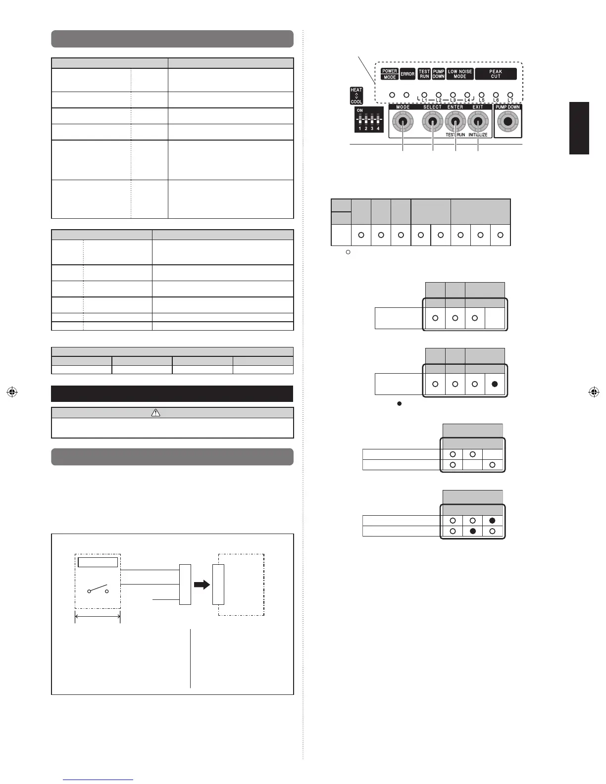
8.2. Description of display
Display lamp
Function or operation method
(1) POWER/MODE Green
Lights on while power on Local setting in
outdoor unit or error code is displayed with
blink.
(2) ERROR Red
Blinks during abnormal air-conditioner
operation.
(3) TEST RUN
(L1)
Orange Lights on during test operation.
(4) PUMP DOWN
(L2)
Orange Lights on during pump down operation.
(5) LOW NOISE MODE
(L3, L4)
Orange
Lights on during “Low noise” function when
local setting is activated.
(Lighting pattern of L3 and L4 indicates
low noise level)
_
Refer to “9. LOCAL
SETTING”.
(6) PEAK CUT
(L5, L6, L7)
Orange
Lights on during “Peak cut” function when
local setting is activated.
(Lighting pattern of L5, L6 and L7 indicates
peak cut level)
_
Refer to “9. LOCAL
SETTING”.
Switch
Function or operation method
SW1 DIP switch
For selecting cooling or heating during test
operation.
Positions 2 to 4 of DIP switch are not used.
SW2 Push switch
To switch between “Local setting” and “Error code
display”.
SW3 Push switch
To switch between the individual “Local settings”
and the “Error code displays”.
SW4 Push switch
To x the individual “Local settings”, “Test run” and
the “Error code displays”.
SW5 Push switch EXIT
SW6 Push switch To start the pump down operation.
DIP switches 1 to 4 at shipment from the factory are set as follows.•
DIP switch
1 2 3 4
COOL OFF OFF OFF
sd
9. LOCAL SETTING
CAUTION
Discharge the static electricity from your body before setting up the switches.
Never touch the terminals or the patterns on the parts that are mounted on the board.
9.1. Low noise mode (Local work)
Outdoor unit may be operated with lower noise than normal operation when following
below local work.
Low noise operation is available by installation of an additional commercially available •
timer or contact input from the ON-OFF switch to the CN19 connector (an external
contact input sold separately) on the control board of the outdoor unit.
* Performance may be decient depending on outdoor temperature or conditions etc.
< Example of circuit diagram >
Outdoor unit control
board
Remote control
panel
Adapter for
external input
CN19
Power supply
Red
White
Black
1
2
3
1
2
3
SW1
Local purchase
(1) Make a circuit of the above gure with
an “Adapter for external input” sold
separately.
(2) Low noise operation can be set up with
the operation of external display portion.
SW1...ON
Level 1
(Shipment condition)
Level 2
SW1...OFF
Normal operation
 Loading...