SERVICE PARTS INFORMATION 5
Check Point 1 : Check rotation of Fan
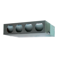
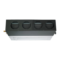
Outdoor unit fan motor
Rotate the fan by hand when operation is off.
(Check if fan is caught, dropped off or locked motor)
>>If Fan or Bearing is abnormal, replace it.
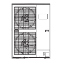
Check Point 2 : Check resistance of Outdoor Fan Motor 1 or 2
Refer to below. Circuit-test "Vm" and "GND" terminal.
(Vm: DC voltage, GND: Earth terminal)
>>If they are short-circuited (below 300 k ), replace Outdoor fan motor and Main PCB.
Pin number
(wire color)
Terminal function
(symbol)
1 (Red)
2
7 (Brown)
3
4 (Black)
5 (White)
DC voltage (Vm)
No function
No function
Earth terminal (GND)
Control voltage (Vcc)
Speed command (Vsp)6 (Yellow)
Feed back (FG)
SERVICE PARTS INFORMATION 4
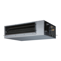
Check Point 1 : Check rotation of Fan
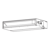
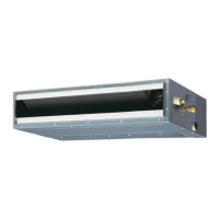
Indoor unit fan motor
Rotate the fan by hand when operation is off.
(Check if fan is caught, dropped off or locked motor)
>>If Fan or Bearing is abnormal, replace it.
02-47
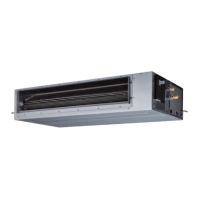
Check Point 2 : Check resistance of Indoor Fan Motor
Check resistance when the main power supply is OFF.
1. Winding coil resistance check (U,V,W) 2. Location circuit resistance check
>> If they are other resistance valule, replace the fan motor
Pin number
(wire color)
Terminal function
(symbol)
1 (Red)
2
3 (White)
4
5 (Black)
Motor Winding U
Motor Winding V
Motor Winding W
Pin number
(wire color)
Terminal function
(symbol)
)wolleY( 1
2 (Blue)
3 (Orange)
4 (Pink)
5 (Gray)
Hu
Hw
Hv
Vcc
GND
U
V
W
Resistance: 2.10
Resistance:
More than 2 M
 Loading...