LO
HI
1. Check if the piping connections are secure.
2. Check that the stems of 2-way valve and 3-way valve are closed
fully.
3. Connect the gauge manifold charge hose to the charging port
of the 3-way valve (side with the projection for pushing in the
valve core).
4. Open the low pressure side valve of the gauge manifold fully.
5. Operate the vacuum pump and start pump down.
6. Slowly loosen the flare nut of the 3-way valve and check if air
enters, then retighten the flare nut.
(When the flare nut is loosened the operating sound of the
vacuum pump changes and the reading of the compound
pressure gauge goes from minus to zero.)
OUTDOOR UNIT
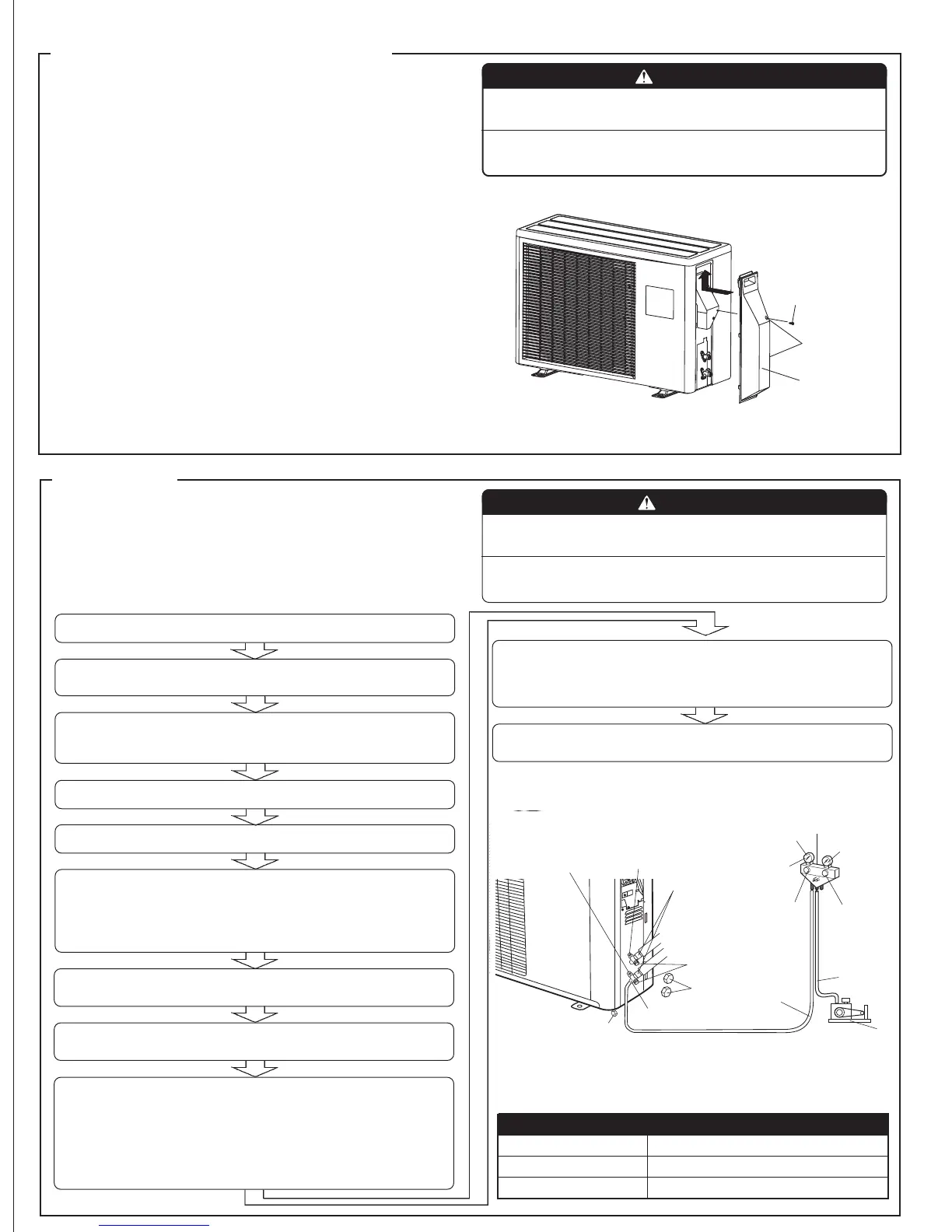
OUTDOOR UNIT INSTALLATION
AIR PURGE
Always use a vacuum pump to purge the air.
Refrigerant for purging the air is not charged in the
outdoor unit at the factory.
Close the high pressure side valve of the gauge manifold fully and do
not operate it during the following work.
● Set the unit on a strong stand, such as one made of concrete blocks
to minimize shock and vibration.
● Do not set the unit directly on the ground because it will cause trou-
ble.
Connector cover removal
● Remove the two mounting screws.
Installing the connector cover
(1) After inserting the three front hooks, then insert the rear hook.
(2) Tighten the two mounting screws.
WARNING
(1) Install the unit where it will not be tilted by more
than 5°.
(2) When installing the outdoor unit where it may ex-
posed to strong wind, fasten it securely.
10. Fully open the valve stems of the 2-way valve and 3-way valve
using a hexagon wrench. (After the valve stem begins to turn,
turn it with a torque of less than 2.17ft•lbs (30 kgf•cm) until it
stops turning.)
11. Firmly tighten the 2-way valve and 3-way valve blank cap and
the charging port cap.
Fig. 9
Tapping screw
Rear hook
Connector cover
Always use the screws as shown above.
Do not select the top and bottom screws incorrectly.
Fig. 10
Flare nut
3-way valve
-0.1 MPa
(-76 cmHg
-1 bar)
High
pressure
side valve
(closed)
CAUTION
(1) Refrigerant must not be discharged into atmos-
phere.
(2) After connecting the piping , check the joints for
gas leakage with gas leak detector.
2-way valve
Gauge manifold
Compound pressure gauge
Pressure gauge
Table 6
Tightening torque
Blank cap (2-way valve) 14.47 to 18.08 ft•lbs (200 to 250 kgf•cm)
Blank cap (3-way valve) 20.25 to 23.15 ft•lbs (280 to 320 kgf•cm)
Charging port cap 9.04 to 11.57 ft•lbs (125 to 160 kgf•cm)
Low pressure
side valve
Blank cap
Charge
hose
Vacuum pump
Valve stem
Charge hose
Charging port cap
Charging port
7. Pump down the system for at least 15 minutes, then check if the
compound pressure gauge reads -0.1 MPa (-76 cmHg, -1 bar).
8. At the end of pump down, close the low pressure side gauge of
the gauge manifold fully and stop the vacuum pump.
9. Slowly loosen the valve stem of the 3-way valve. When the
compound pressure gauge reading reaches 0.1-0.2 MPa,
retighten the valve stem and disconnect the charge hose
from the 3-way valve charging port.
(If the stem of the 3-way valve is opened fully before the
charge hose is disconnected, it may be difficult to disconnect
the charge hose.)