Trouble shooting 2
INDOOR UNIT Error Method:
Detective Actuators:
Detective details:
Forecast of Cause:
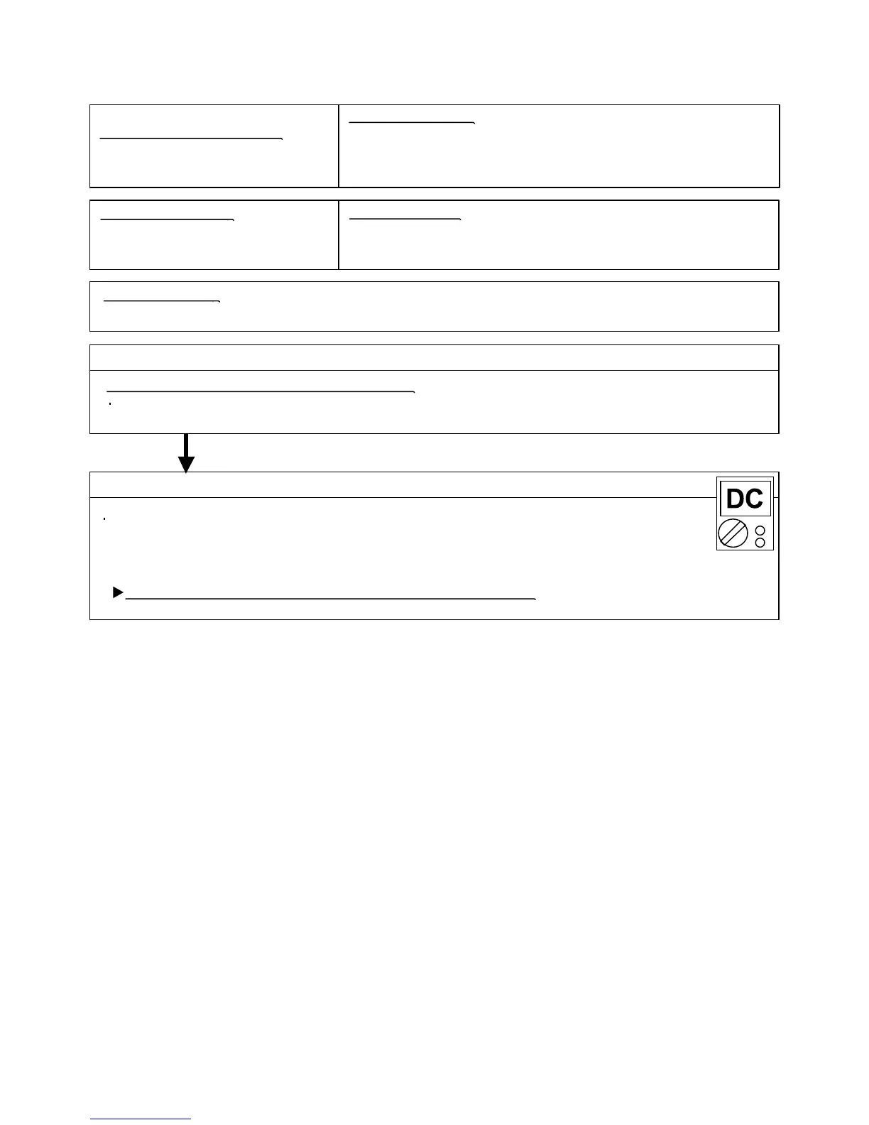
Check Point 2 : Check Remote Control and Controller PCB
Check Point 1 : Check the connection of terminal
OKOK
Indicate or Display:
Remote controller communication
error
Indoor unit Controller PCB
Wired Remote Control
1. Terminal connection abnormal 2. Wired Remote Control failure 3. Controller PCB failure
After turning off the power, check & correct the followings.
Check the connection of terminal between remote control and Indoor unit,
and check if there is a disconnection of the cable.
Upon correcting the removed connector or mis-wiring, reset the power.
Check Voltage at CN305 (terminal 1-3) of UTY-XCBXZ1(Communication kit).
(Power supply to Remote Control)
>> If it is DC13V, Remote Control is failure. (Controller PCB is normal) >> Replace Remote Control
>> If it is DC 0V, Controller PCB is failure. (Check Remote Control once again) >> Replace Controller PCB
When the indoor unit cannot receive the signal from Wired Remote Control
more than 1minute during normal operation.
02-06
Outdoor Unit : No indication
Indoor Unit : Operation lamp: 1 time Flash, Timer lamp: 2 times Flash
Economy lamp: Continuous flash.
ERROR CODE : [E : 12]
 Loading...