Trouble shooting 5
INDOOR UNIT
INDOOR UNIT Error Method:
Indicate or Display:
Detective Actuators:
Detective details:
Forecast of Cause :
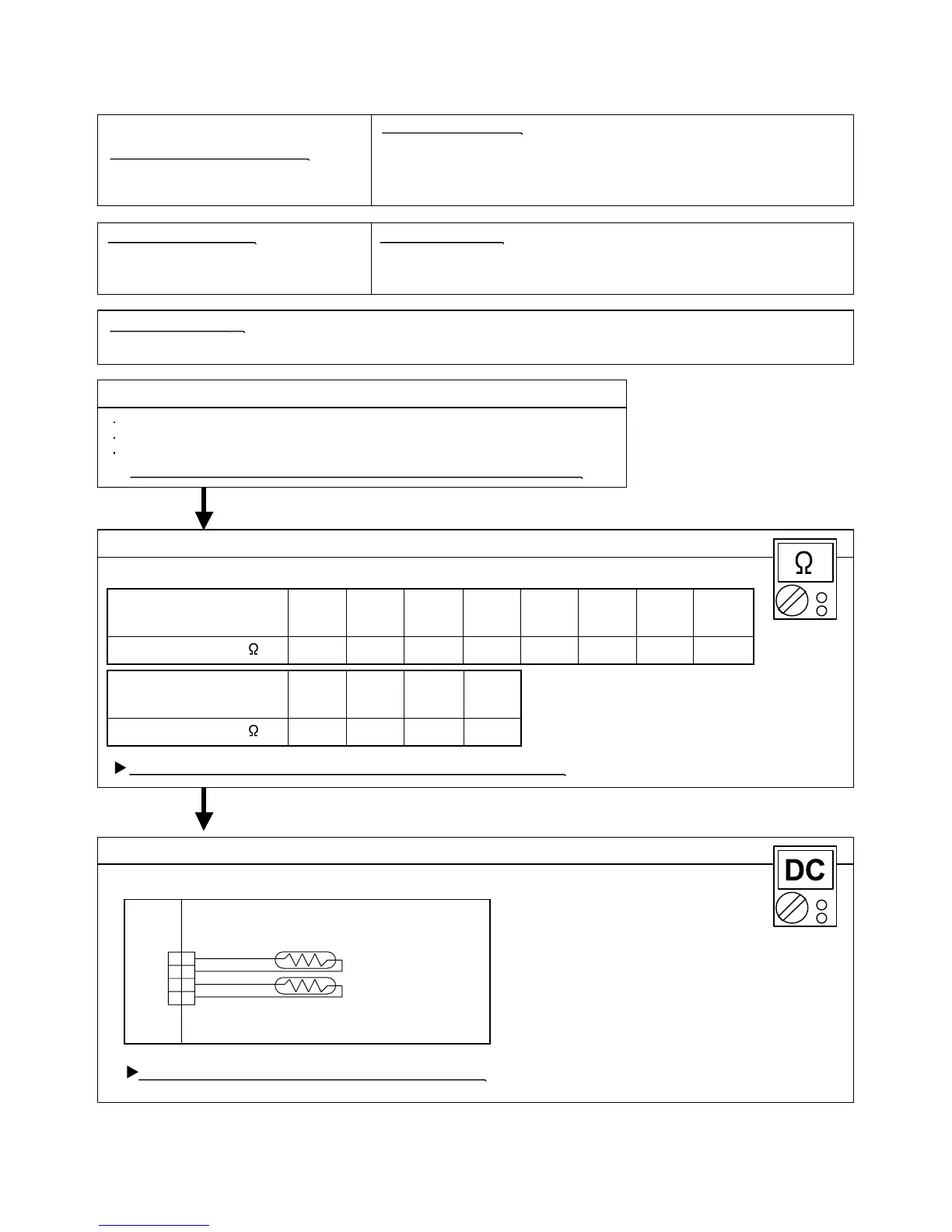
Check Point 2 :Check Point 2 : Remove connector and check Thermistor resistance value
Check Point 1 : Check connection of Connector
Check Point 3 :Check Point 3 : Check voltage of Controller PCB (DC5.0V)
10.012.515.820.225.933.644.058.2Resistance Value (k )
Temperature
OK
OK
5.36.58.0Resistance Value (k )
Temperature
Room Temperature Sensor Error
Indoor unit Controller PCB
Room Temperature Thermistor
When Room Temperature Thermistor open or short-circuit is detected.
1. Connector connection failure 2.Thermistor failure 3. Controller PCB failure
Check if connector is removed.
Check erroneous connection.
Check if thermistor cable is open.
>>Upon correcting the removed connector or mis-wiring, reset the power.
Thermistor Characteristics (Approx. value)
If Thermistor is either open or shorted, replace it and reset the power.
Make sure circuit diagram of indoor unit and check terminal voltage at Thermistor (DC5.0V)
If the voltage does not appear, replace Controller PCB.
02-09
25°C20°C15°C10°C5°C0°C-5°C-10°C
40°C
4.4
45°C35°C30°C
Outdoor Unit : No indication
Indoor Unit : Operation lamp: 4 times Flash, Timer lamp: 1 time Flash
Economy lamp: Continuous flash.
ERROR CODE : [E : 41]
THERMISTOR
(ROOM TEMP.)
THERMISTOR
(PIPE)
BLACK
CN4
1
2
3
4
1
2
3
4
BLACK
BLACK
BLACK
 Loading...