Do you have a question about the Fujitsu ASY12LSBCW and is the answer not in the manual?
Details power source, running current, input watts, E.E.R., COP, and moisture removal for the units.
Describes compressor type, discrimination, and refrigerant type and charge amount.
Lists fan motor power source and speed variations (RPM) for indoor and outdoor units.
Provides physical dimensions (HxWxD) for indoor and outdoor units in mm.
Shows the gross and net weight in kg for both indoor and outdoor units.
Specifies the noise levels in dB for indoor and outdoor units at different settings.
Details refrigerant pipe length, full charge amount, and additional refrigerant.
Specifies the diameter for liquid (1/4") and gas (3/8") refrigerant pipes.
Details the electrical circuit for the indoor unit, including power, fans, and PCBs.
Outlines the electrical circuit for the outdoor unit, including components like the compressor and fan motor.
Describes the function of jumper wires (JM1, JM2) for custom code and auto restart settings.
Covers errors related to serial communication signals, including reverse and forward signal issues.
Details errors caused by open or shorted thermistors in both indoor and outdoor units.
Includes issues like forced automatic SW welding, main relay welding, and power interruption.
Details errors like current trip, CT abnormal, compressor rotation, and fan drive system abnormal.
Covers issues such as abnormal lock or rotation of the indoor fan motor.
Includes errors related to discharge temperature and high pressure rise in the refrigerant cycle.
Details errors related to active filter voltage, active filter foliage, and PFC circuit abnormalities.
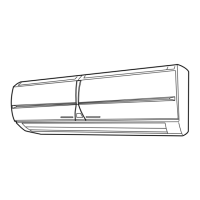
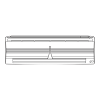
Provides illustrated steps for disassembling the indoor unit components.
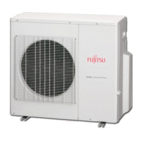
Illustrates the components and assembly of the outdoor unit.
Lists part numbers and descriptions for various components of the indoor unit.
Lists part numbers and descriptions for various components of the outdoor unit.
Lists standard accessories included with the unit, such as wall hook bracket and remote control.
| Brand | Fujitsu |
|---|---|
| Model | ASY12LSBCW |
| Category | Air Conditioner |
| Language | English |