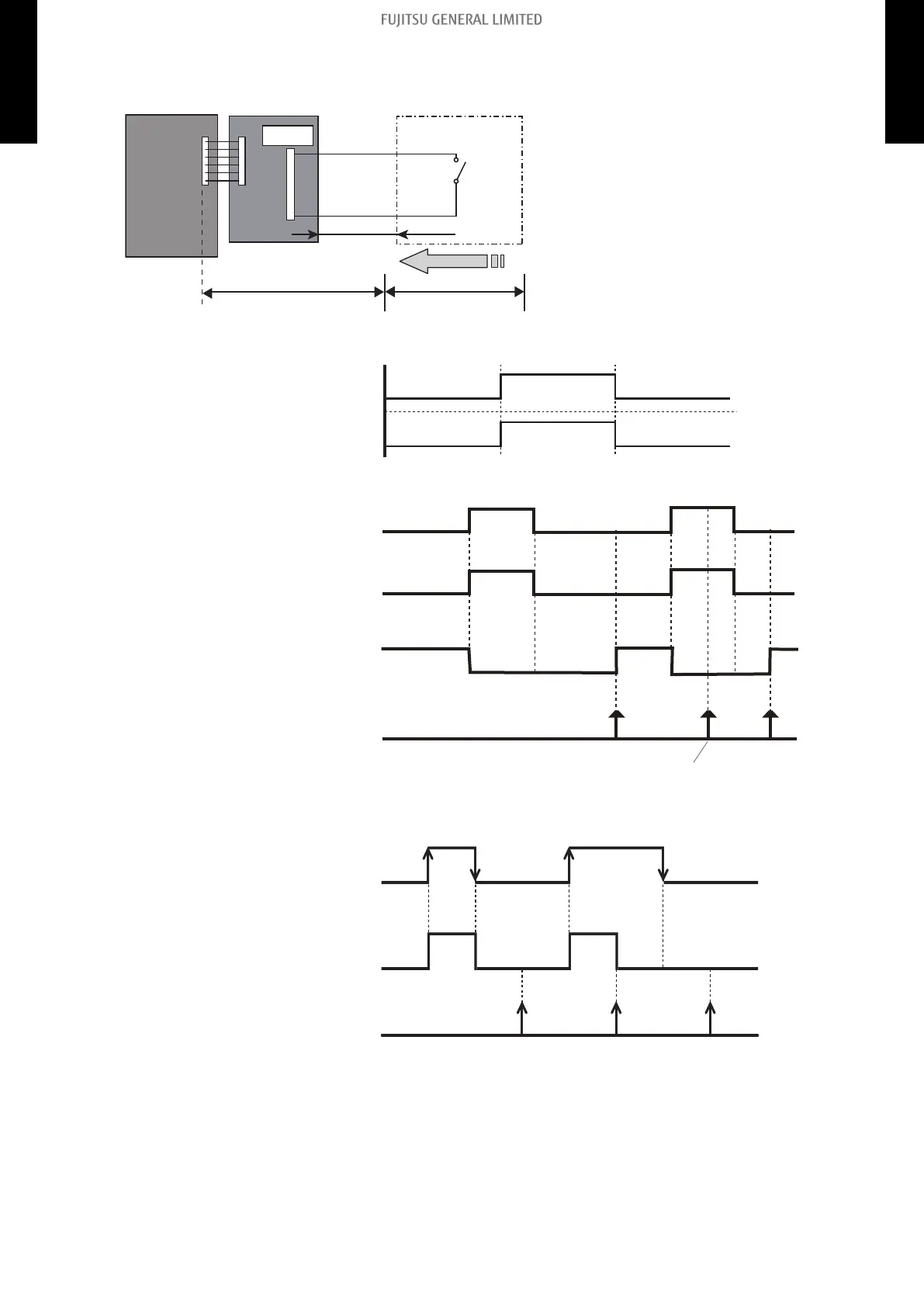
• Circuit diagram example
Signal
Locally purchased
Indoor unit
control PCB
Communication kit
Optional parts
Connector
1
3
10 m*
Connected unit
Example: Switch
• Contact capacity: DC 24 V or more,
10 mA or more.
• *: Make the distance from the PCB to
the connected unit within 10 m.
• Use non-polar relays and switches.
– When function setting is “Operation/Stop” mode
Operation
Stop
On
Off
Input signal
Indoor unit
– When function setting is “Forced stop” mode
Remote controller
On On On
Input signal
Indoor unit
Command
Remote control
operation invalidity
On
Off
Operation
Stop
Forced stop
Normal
– When function setting is "Operation/Stop" mode 2
On
Input
Off
Operation
Indoor unit
Stop
(R.C. disabled)
Remote controller
On OnOff
NOTE:
When "Operation/Stop" mode 2 function is used with forming a remote controller
group, connect the same equipment to each indoor unit within the group.
- 21 -
8-1. External input 8. External input and output
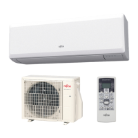
WALL MOUNTED
ASYG07-14KMCC
WALL MOUNTED
ASYG07-14KMCC
 Loading...