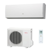
Do you have a question about the Fujitsu ASYG07KMTA and is the answer not in the manual?
Detailed electrical specifications including power, current, and EER for indoor and outdoor units.
Specifies fan speeds (rpm) for different operation modes and conditions.
Provides noise level data (dB) for cooling and heating operations for indoor and outdoor units.
Details compressor type, refrigerant type (R32), and charge information.
Lists net and shipping weights for indoor and outdoor units.
Lists physical dimensions (H x W x D) of indoor and outdoor units.
Visual representation of indoor unit dimensions and key features like drain hose.
Visual representation of outdoor unit dimensions and key features for different models.
Refrigerant circuit diagram for specific indoor/outdoor model combinations.
Refrigerant circuit diagram for specific indoor/outdoor model combinations.
Refrigerant circuit diagram for specific indoor/outdoor model combinations.
Wiring diagram for the overall system, showing connections between main PCB, power source, and components.
Detailed diagram of printed circuit board layouts and connections for indoor and outdoor units.
Lists error codes and corresponding indicator lamp patterns for diagnostics.
Step-by-step guidance for diagnosing issues based on error codes.
Procedures for diagnosing problems when no error code is displayed.
Exploded views and part numbers for indoor unit components like remote control and filters.
Exploded views and part numbers for outdoor unit components like fan and compressor.
List of accessories included with the indoor and outdoor units, such as remote controllers and batteries.
Detailed explanation of cooling mode operation, compressor frequency, and fan control.
Detailed explanation of heating mode operation, compressor frequency, and fan control.
Explanation of the dry mode function and its compressor frequency control.
Details on indoor fan speed control and operation modes like Auto, Quiet, and Hi.
Details on outdoor fan speed control based on operating conditions.
How to adjust vertical and horizontal louvers and swing operation.
Explains compressor frequency control, startup, and limitations by outdoor temperature.
Explains ON/OFF, Program, and Sleep timer functions for remote controllers.
How the electronic expansion valve operates and its control based on conditions.
Procedure for performing a system test operation using remote controls.
Covers Auto Restart, Manual Auto, Forced Cooling operations.
Explains the process of heating the compressor before operation.
Details the operation when the 10°C HEAT setting is activated.
Explanation of the energy-saving economy mode.
Conditions for starting and ending defrost cycles based on temperature and time.
Describes protection mechanisms like discharge gas temp, current release, and antifreezing.
Configuration settings for indoor unit functions like address and filter sign display.
Tables showing thermistor resistance vs. temperature for diagnostic purposes.
| Type | Air conditioner indoor unit |
|---|---|
| Timer | Yes |
| Multi-split | No |
| Product color | White |
| Gas hose diameter | 9.5 mm |
| Hose length (max) | 15 m |
| Inverter technology | - |
| Liquid hose diameter | 6.35 mm |
| Dehumidifying capacity | 1 l/h |
| Air conditioner functions | Cooling, Heating |
| Cooling capacity in watts (max) | 2580 W |
| Cooling capacity in watts (min) | 430 W |
| Heating capacity in watts (max) | 3000 W |
| Heating capacity in watts (min) | 500 W |
| Cooling capacity in watts (nominal) | 1720 W |
| Cooling energy efficiency (EER, W/W) | 4.43 |
| Heating energy efficiency (COP, W/W) | 4.52 |
| Seasonal efficiency rating (cooling) (SEER) | 7.4 |
| Heating capacity in watts (nominal) (Warmer heating season) | - W |
| Heating capacity in watts (nominal) (Average heating season) | 2000 W |
| Seasonal efficiency rating (heating) (SCOP) (Average heating season) | 4.1 |
| AC input voltage | 230 V |
| Current (cooling) | 6.5 A |
| Current (heating) | 9 A |
| AC input frequency | 50 Hz |
| Design load (cooling) | 2 kW |
| Energy efficiency class (cooling) | A++ |
| Hourly energy consumption (cooling) | - kWh |
| Design load (heating) (Warmer heating season) | - kW |
| Design load (heating) (Average heating season) | 2.3 kW |
| Energy efficiency class (heating) (Average heating season) | A |
| Indoor unit type | Wall-mountable |
| Indoor unit depth | 222 mm |
| Indoor unit width | 834 mm |
| Indoor unit height | 270 mm |
| Indoor unit weight | 10000 g |
| Indoor units quantity | 1 |
| Cooling airflow (indoor unit) | 650 m³/h |
| Indoor unit sound power level | 38 dB |
| Indoor unit noise level (low speed) | 29 dB |
| Indoor unit noise level (high speed) | 41 dB |
| Outdoor unit noise level | - dB |