Do you have a question about the Fujitsu ASYG14LMCB and is the answer not in the manual?
Detailed electrical specifications including type, capacity, power, current, and input watts.
Noise level measurements for both indoor and outdoor units during cooling and heating operations.
Information on compressor type, refrigerant, precharged amount, and piping specifications.
Specifications for the fan motor, including power source and speed (RPM) for different operating modes.
Detailed circuit diagram for the indoor unit's Printed Circuit Board (PCB).
Schematic diagram of the main PCB for the indoor unit, detailing component connections.
Circuit diagram for the indicator PCB of the indoor unit, showing LED and sensor connections.
Circuit diagram for the communication PCB, likely for remote control or external connectivity.
Indicates error codes based on blinking patterns of indoor unit operation and timer lamps.
Shows error codes displayed on the wired remote control, including specific error codes and descriptions.
Diagram and part numbers for the indoor unit's control box and associated components.
Exploded view and part numbers for the indoor unit's evaporator fan assembly.
Diagram and part numbers for the indoor unit's casing and related structural components.
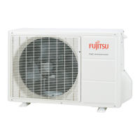
Diagram and part numbers for various components of the outdoor unit, including PCB, compressor, and valves.
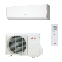
| Model | ASYG14LMCB |
|---|---|
| Brand | Fujitsu |
| Category | Air Conditioner |
| Type | Split System |
| Cooling Capacity | 4.0 kW |
| Heating Capacity | 5.0 kW |
| Energy Efficiency Class (Cooling) | A++ |
| Energy Efficiency Class (Heating) | A+ |
| Refrigerant | R32 |
| Power Supply | 220-240V, 50Hz |
| Indoor Unit Weight | 9.5 kg |
| Airflow Rate (Indoor) | 10.5 m³/min |
| Airflow Rate (Outdoor) | 2100 m³/h |
| Energy Efficiency Rating (Cooling) | 6.1 |
| Indoor Unit Noise Level (Low) | 19 dB(A) |
| Outdoor Unit Dimensions (HxWxD) | 550 x 780 x 285 mm |
| Air Flow (Indoor) | 10.5 m³/min |
| Indoor Unit Noise Level | 21 dB(A) |