Error status output
Air conditioner error status signal can be output.
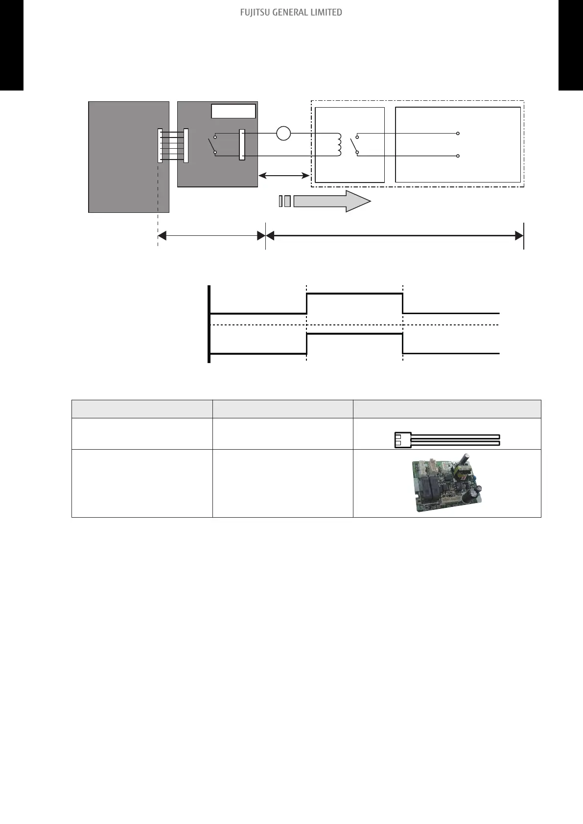
• Circuit diagram example:
Locally purchasedOptional parts
Example: Display
Indoor unit
control PCB
Communication kit Connected unit
Example: Relay unit
1
2
Signal
Relay
power supply
V
Connector
10 m*
DC 24 V
– *: Make the distance from the PCB to the connected unit within 10 m.
– Relay spec: Max. DC 24 V, 10 mA to less than 500 mA.
On
Off
Error
Normal
Error status
Output signal
• Optional part:
Part name Model name Exterior
External Connect Kit UTY-XWZXZ5
External output wire
Communication Kit UTY-TWBXF2
* For operating the external function, the wall mounted type requires the communication kit in addi-
tion to the wire (UTY-XWZXZ5).
- 144 -
12-3. Wall mounted type (KMTB and KMCC) 12. External input and output
2-UNIT
MULTI-SPLIT TYPE
2-UNIT
MULTI-SPLIT TYPE
 Loading...