2-3. E: 12. Wired remote controller communication error (Indoor
unit)
Indicator Indoor unit
Operation indicator 1 time flash
Timer indicator 2 time flash
Economy indicator Continuous flash
Error code E: 12
Detective actuator
Indoor unit Main PCB When the indoor unit cannot receive the signal from
wired remote controller more than 1 minute during
normal operation.
Wired remote control
Forecast of cause
Terminal connection abnormal
Wired remote control failure
Main PCB failure
Check point 1. Check the connection of terminal
After turning off the power, check & correct the followings.
• Check the connection of terminal between wired remote controller and indoor unit, and check if
there is a disconnection of the cable.
↓
Check Point 1-2 : Check the wired remote controller and main PCB
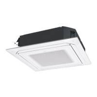
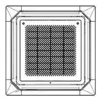
[Compact cassette and floor types]
Check voltage at CN14 (terminal 1—3, terminal 1—2) of main PCB. (Power supply to the remote
controller)
• If it is DC 12 V, the remote controller is failure. (Main PCB is normal)
– Replace the remote control
• If it is DC 0 V, the main PCB is failure. (Check remote controller once again)
– Replace the main PCB
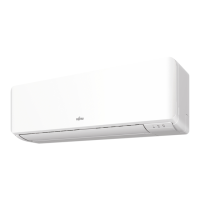
[Wall mount type for KGTB, KGTE, KMCE, KETA, KETE]
Check voltage at CN300 (terminal 1—2) of main PCB or communication PCB. (Power supply to the
remote controller)
• If it is DC 12 V, the remote controller is failure. (Main PCB is normal)
– Replace the remote control
• If it is DC 0 V, the main PCB is failure. (Check remote controller once again)
– Replace the main PCB
[Wall mount type for KMTB, KMCC]
Check voltage at CNC01 (terminal 1—3) of main PCB or communication PCB. (Power supply to the
remote controller)
• If it is DC 13 V, the remote controller is failure. (Main PCB is normal)
– Replace the remote control
• If it is DC 0 V, the main PCB is failure. (Check remote controller once again)
– Replace the main PCB
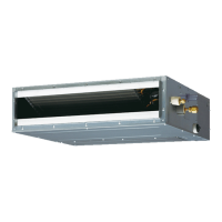
[Mini duct and Slim duct types]
Check voltage at CN300 (terminal 1—3, terminal 1—2) of main PCB. (Power supply to the remote
controller)
• If it is DC 12 V, the remote controller is failure. (Main PCB is normal)
– Replace the remote control
• If it is DC 0 V, the main PCB is failure. (Check remote controller once again)
– Replace the main PCB
2-3. E: 12. Wired remote controller communication error (Indoor unit) - (03-15) - 2. Troubleshooting with error code
TROUBLESHOOTING
TROUBLESHOOTING
 Loading...