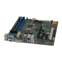
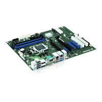
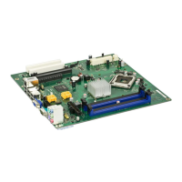
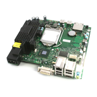
Pin assignment of internal ports
A26361-D1837-Z120-1-7419, Edition 1 English - 15
Audio Input
1
Pin Signal
1 Left audio input
2 Audio GND
3 Audio GND
4 Right audio input
Audio port front
1 2
Pin Signal Pin Signal
1 Micro input 2 Analogue GND
3 Micro bias 4 Analogue VCC
5 Right line output 6 Right line return
7 not connected 8 Key
9 Left line output 10 Left line return
If the audio front panel is not used, you must plug jumpers on pin pairs 5/6 and 9/10.
USB - dual channel
1 2
11
12
Pin Signal Pin Signal
1 Key 2 Chipcard reader on or not
connected
3 VCC 1 or 3 4 VCC 2 or 4
5 Data negative 1 or 3 6 Data negative 2 or 4
7 Data positive 1 or 3 8 Data positive 2 or 4
9 GND 10 GND
11 Key 12 not connected