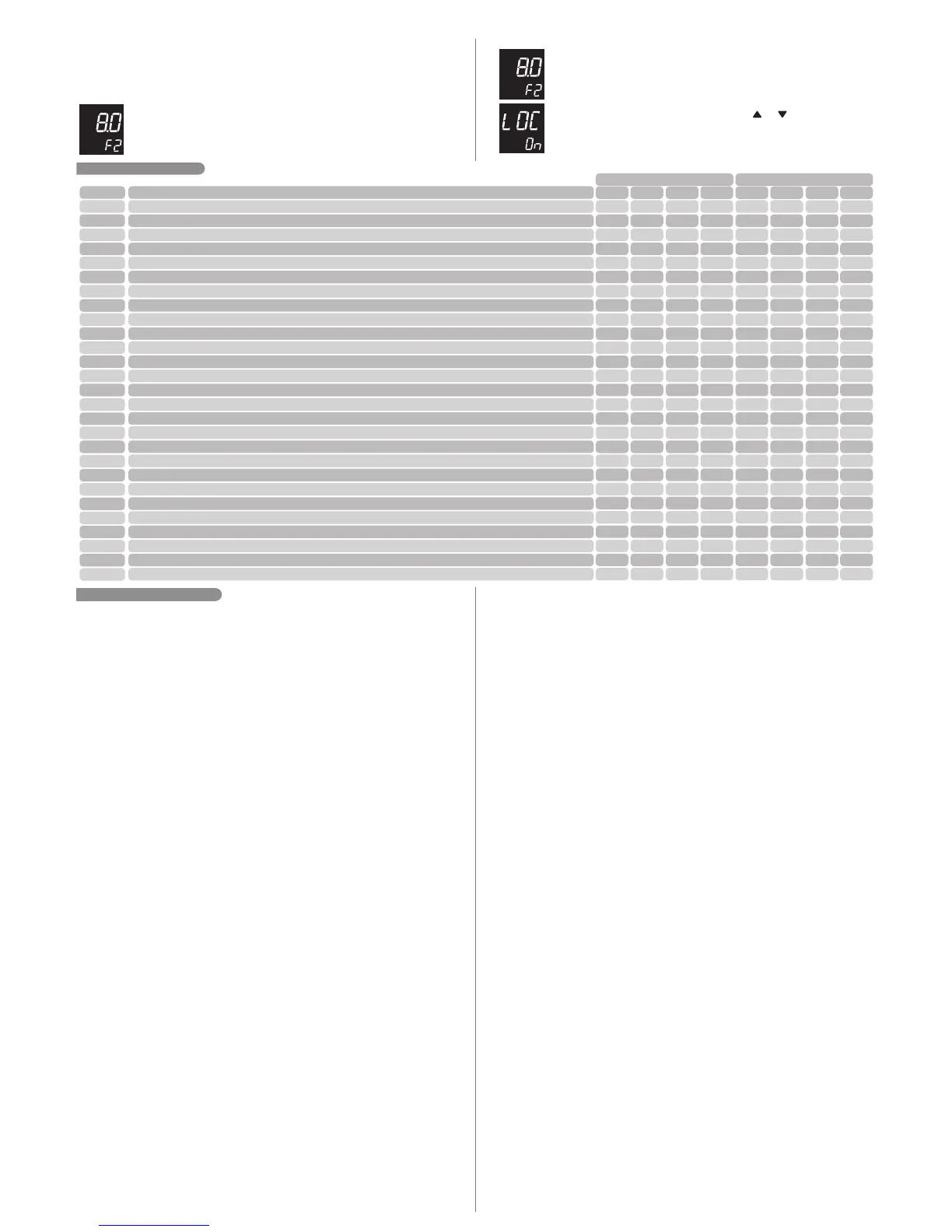
6.2 TABLE OF PARAMETERS
Min
Max
Unit
Min
Max
Unit
Standard
CELSIUS
FAHRENHEIT
Fun
[CoDE]
[,F01]
[,F02]
[,F03]
[,F04]
[,F05]
[,F06]
[,F07]
[,F08]
[,F09]
[,F10]
[,F11]
[,F12]
[,F13]
[,F14]
[,F15]
[,F16]
[,F17]
[,F18]
[,F19]
[,F20]
[,f21]
[,f22]
[,f23]
[,f24]
[,f25]
[,f26]
Standard
Description
Access code
Preferential indication
Differential (T1-T2) to turn on the pump
Differential (T1-T2) to turn off the pump
Antifreeze temperature (T1) to turn on the pump
Antifreeze minimum time
Overheating temperature (T1) to turn off the pump
Overheating temperature (T2) for turn off the pump
Overheating temperature hysteresis (T2) to restart the pump
Maximum pump on time in manual mode
Temperature in sensor T3 to turn off cooling in vacation mode
Vacuum tube Function
Pump on time in the vacuum tube function
Pump off time in the vacuum tube function
Minimum temperature (T1) to switch the pump on in the vacuum tube function
Maximum differential (T1-T2) for protection against thermal shock in the vacuum tube function
Hysteresis of the support temperature (T3) (TEMP parameter)
Minimum value allowed for setting the support temperature (TEMP parameter)
Maximum value allowed for setting the support temperature (TEMP parameter)
Time of support manual support activation
Operation mode for the support event schedule
Outlet of the support associated to antifreeze T1
T1 Sensor indication displacement (Offset)
T2 Sensor indication displacement (Offset)
T3 Sensor indication displacement (Offset)
Time for function block
Display backlight Intensity (Backlight)
0
DIF
1.0
1.0
no (-19)
no (0)
0.0
0.0
0,1
1
0.0
Off
10
1
0,0
0,1
0.1
0.0
0.0
no (0)
1b1
Off
-5.0
-5.0
Off(-5.1)
no (3)
Eco (0)
999
T3
40.0
40.0
10.0
600
200
105
20,0
720
105
On
999
999
105,0
70,0
20.0
105
105
600
1t7
On
5.0
5.0
5.0
30
10
-
-
ºC
ºC
ºC
s
ºC
ºC
ºC
min.
ºC
-
s
min.
ºC
ºC
ºC
ºC
ºC
min
-
-
ºC
ºC
ºC
s
-
0
T3
8.0
4.0
8.0
60
90.0
70.0
1,0
360
105.0
Off
20
30
20,0
30,0
1.0
0.0
50.0
120
1t7
Off
0.0
0.0
0.0
4
8
0
DIF
1
1
no (-2)
no (0)
32
32
1
1
32
Off
10
1
32
1
1
32
32
no (0)
1b1
Off
-9
-9
Off (-9)
no (3)
1
999
T3
72
72
50
600
392
221
36
720
221
On
999
999
221
126
36
221
221
600
1t7
On
9
9
9
30
10
-
-
ºF
ºF
ºF
s
ºF
ºF
ºF
min.
ºF
-
s
min.
ºF
ºF
ºF
ºF
ºF
min
-
-
ºF
ºF
ºF
s
-
0
T3
14
7
46
60
194
158
1
360
221
Off
20
30
68
54
1
32
122
120
1t7
Off
0
0
0
10
Eco (0)
To leave the menu and return to normal operation (temperature indication) hold the SET
key (long touch) until [----] appears.
- Upon accessing the parameter settings, the upper display will flash and over
it the SET icon is displayed, indicating that it is possible to change the
parameter value.
Observations:
am pm
- If the 123 code has not been inserted, upon accessing the parameter settings
the icon will be displayed over the upper display, indicating that the
setting is locked.
- With active function block, upon pressing the or keys to change the
function value, the controller will display the [,LOC] [,,On]message on
the screen and it won't be possible to perform the parameter setting.
SET
LOC
LOC
LOC
6.3 PARAMETER DESCRIPTION
[Code]- Access Code (123):
It is necessary when you wish to change the advanced settings' parameters. To only visualize
the set parameters it is not necessary to insert this code.
[,F01] - Preferential Indication:
This function allows choosing the temperature that will normally be displayed. You may choose
between:
[,DIF]- Differential T1-T2. Shows how many levels is the difference between the
solar collectors (T1) and the pool or thermal reservoir (T2).
[,,T1]- Collectors' temperature (T1).
[,,T2]- Temperature of the thermal reservoir (T2).
[,,T3]- Support temperature (T3) (if activated).
[,F02] - Differential (T1-T2) to turn the pump on:
Allows configuring the temperature difference between the solar collector and the thermal
reservoir to activate the circulation pump. As the collectors receive energy, the temperature in
Sensor T1 increases when this temperature is at a determined value above the sensor T2
temperature, the pump is turned on and circulates the heated water, storing it in the reservoir.
[,F03] - Differential (T1-T2) to turn off the pump:
It allows setting the temperature difference between the solar collector and the thermal reservoir
to turn off the circulation pump. With the pump on, the temperature difference between the
collector and the reservoir (T1-T2) tends to reduce. When this value falls to a determined value,
the pump is turned off, stopping water circulation.
[,F04]- Antifreeze temperature (T1) for turn on the pump:
When the temperature of (T1) collectors is too low (i.e.: winter nights) the pump is turned on,
according to the temperature set to this parameter, to prevent the water from freezing in the solar
collector and thus damaging them. The hysteresis of this control is fixed and defined at 2.0ºC. To
disable this function move the setting to the minimum until it is displayed [,,No].
[,F05] - Minimum antifreeze Time:
This minimum time for the pump turned on serves as security, to assure that the water passes
through all of the collectors. Even if sensor T1 temperature exceeds the antifreeze temperature
(parameter [,F04]), the controller respects the time programmed in this parameter. A very
used function in large works by the quantity of plates installed. To disable this function dislocate
the settings to a minimum until [,,No] is displayed.
[,F06]- Overheating temperature (T1) to turn off the pump:
When the temperature in (T1) collectors is above the value set for this parameter, the pump is
turned off in order to prevent the overheated water to circulate through the pipes and thus
damage them, in case PVC pipes are used for example. The hysteresis of this control is fixed
and defined at 2.0ºC.
[,F07] - Overheating temperature (T2) to turn off the pump:
This is the maximum temperature desired in the reservoir, above which the water circulation
pump will not operate. This is a safety measure to protect the hydraulic installation in case of
overheating. The hysteresis of this control is fixed and defined at 2.0ºC.
[,F08] - :Overheating temperature hysteresis (T2) to restart the pump
If the pump is off due to overheating in sensor T2 this function can define a temperature range
within which the pump will remain off.
Exemple: application in temperature control of swimming pools.
[,F07] = 30.0ºC
[,F08] = 1.0ºC
The swimming pool will be heated through the water circulation pump until sensor T2 temperature
reaches 30.0ºC. When this value is reached the circulation pump switched off. When the
temperature drops to 29.0ºC, the swimming pool is heated again (30.0ºC - 1.0ºC = 29.0ºC)
[,F09] - Maximum pump on time in manual mode:
It is the time the pump will remain in manual mode. After this period, the controller assumes the
AUT (AUTOMATIC) mode.
[,F10] - Temperature in sensor T3 to turn off the cooling vacation mode:
Has the purpose of cooling the thermal reservoir during the night, when Vacation mode is
activated, whenever the sensor T3 temperature is above the value set in this parameter and the
temperature difference between the collector (T1) and the reservoir (T2) reaches -4,0ºC (fixed).
The pump is then turned on, using the collector as a radiator to cool the swimming pool water.
When the differential (T1-T2) lowers below -2.0ºC (fixed) or the support temperature (T3) lowers
below this parameter's temperature, the pump is turned off. The hysteresis of this control is fixed
and defined at 2.0ºC.
NOTE: When the T3 sensor in [,F24] is deactivated, the temperature of the support is now
referenced by sensor T2.
[,F11] - Vacuum tube function:
In case this function is enabled, the controller activates the pump for time set in [,f12] and
keeps the pump off for the time set in [,f13]. In order to perform this control, the collector (T1)
temperature must be higher than the value set in [,f14] and observe the maximum differential
set in [,f15].
There are models of vacuum tube collectors that do not allow the direct measure of collector
temperature, for they do not have a prediction for immersion sensors. For a correct measure of the
water temperature at the collector outlet, it is necessary that a minimum water flow occurs.
Therefore the solar circuit should activate the pump in regular intervals so that the heated water
from the collector reaches the sensor T1.
Obs.: the controller prioritizes the protection settings (overheating), ignoring the vacuum tube
function, when they occur.
[,F12]- :Pump on time in the vacuum tube function
It is the time the pump will remain on when the vacuum tube function is active.
[,F13]- :Pump off time in the vacuum tube function
It is the time the pump will remain off when the vacuum tube function is active.
[,F14]- :Minimum temperature (T1) to switch the pump on in the vacuum tube function
It is the minimum temperature (T1) allowed to activate the vacuum tube function.
[,F15]- Maximum differential (T1-T2) for protection against thermal shock in the vacuum
tube function:
It is the maximum temperature difference allowed between T1 and T2 to switch the circulation
pump on. When the vacuum tube function is enabled, the protection against thermal shock is
activated, which prevents the circulation pump from being switched on when the collector
temperature is much higher than the tank.
 Loading...