MCSOLADVANCONNBMP03-02T-19055
DIFFERENTIAL THERMOSTAT
FOR SOLAR HEATING
Ver. 03
BMP Advanced
Have this manual in the palm of
your hand through the FG Finder.
1. DESCRIPTION
O Microsol BMP Advanced is a differential thermostat for c o n n e c t
solar heating, with up to four sensors and four outputs, one of which is analog, which
control the water circulation pump and the thermal support. It has a clock and event
schedule for rational and efficient use of thermal support, in addition to an exclusive
Holidays mode that adds protection and energy savings to the SHS (solar heating system)
in periods of low hot water consumption. The controller has functions that prevent the
water from overheating and freezing in the solar collector, in addition to protecting the
access to settings.
The Microsol Advanced line has NFC approximation data conect se caractisda
transfer technology for configuring and diagnosing your heating system through the
exclusive Microsol app. Connect................
It is characterized by a unique design for use in residential environments, by the ease of
operation with touch keys for easy access to the main features of the controller and by the
use of a customized display.
3. APLICAÇÃO
- Solar heating with auxiliary heating system.
2. APPLICATION
3. TECHNICAL SPECIFICATIONS
Microsol BMP Advanced
1
2 3 4
6
7
8
9
10
11
4. INTENDED USE
4.1 INTERFACE
1. Display
2. Pump Indication
3. Auxiliary 1 Indication
4. Auxiliary 2 Indication
5. NFC area
6. Auxiliary 1key
7. Auxiliary 2 key
8. Up key
9. Down key
10. PUMP key
11. SET key
Output status of LEDs:
• OFF = OFF
• = Automatic (AUT) Green
• Yellow = Manual (MAN)
• Yellow/White = Manual in WEEKEND mode
Each controller output has a colored LED to indicate the state and output mode. The color
of the LED indicates the mode selected for the output. The flashing led indicates that the
output is on.
6. OPERATIONS
6.1 KEYMAP
Short press - Acess user settings.
Long press (4 seconds) - Access advanced settings.
Short press - Checks the status of the function lock.
Long press (4 seconds) - Enables/Disables function lock.
See chapter 6.6 Function lock.
Short press - Toggles the temperature display (DIF, T1, T2, T3, T4,
TIME). Shows time remaining when in manual mode.
Long press (4 seconds) - Inhibits audible alarm.
Short press - (AUT/MAN). Changes pump mode
Long press (4 seconds) - Turns off the pump (OFF).
Short press - Changes auxiliary 1 mode (AUT/MAN/OFF).
Long press (4 seconds) - Enables/Disables Weekend mode on
auxiliary 1.
Short press - Changes auxiliary 2 mode (AUT/MAN/OFF).
Long press (4 seconds) - Enables/Disables Weekend mode on
auxiliary 2.
Long press (4 seconds) - Enables/Disables Holidays mode.
+
6.2 PUMP OPERATION MODE
With each press of the Key, the water pump operating mode is changed. The water ??
circulation pump can operate in three different modes:
Operating Temperature
Operating humidity
Control output
Control temperature
104 x 160 x 34mm (4.09” x 6.30” x 1.34”)
Resolution
Dimensions
0,1ºC between -10 and 100ºC and 1ºC in the rest of the range
0,1ºF between -10 and 100ºF and 1ºF in the rest of the range
PUMP - , max . 1HP at 220Vca (½ HP at 127 Vca)Relay output
AUX 1 - Relay output, max . 16A,3500W resistor at 220Vca
(1750W at 127 Vca)
AUX 2 - Relay output, max . 5A, 1100W resistor at 220Vca
(630W at 127 Vca)
Warning: The sum of the loads must not exceed 24A.
T1: – Sensor SB59, white cable, Silicone, 1m Solar Collector
T2: Thermal reservoir – Sensor SB19, 2,5m
T3: Support – Sensor SB19, 2,5m
T4: Support – Sensor SB19, 2,5m
10 a 90% UR ( )without condensation
Power
115Vac ±10%(50/60Hz) or 230Vac ±10%(50/60Hz)
Sensor T1: -20 to 200ºC / -4 to 392ºF
Sensor T2: -20 to 105ºC / -4 to 221ºF
Sensor T3: -20 to 105ºC / -4 to 221ºF
Sensor T4: -20 to 105ºC / -4 to 221ºF
0 to 50°C (32 to 122°F)
Sensors
4.2 OUTPUT INDICATION
Press for
4 seconds
Short press
AUT
OFF
MAN
Short press
OFF: Circulation pump off.
AUT: Circulation pump in automatic
mode operating according to settings.
MAN: Circulation pump on.
5. NFC FUNCTIONALITY
NFC is a technology for data exchange and wireless communication.
Perfor m contr oller set up and verif y your data using the M i c r o sol
1111111111111111111 app with a compatible smartphone.
For more information, visit the website http://microsolconnect.fullgauge.com/ or scan the
QRcode with your cell phone.
Attention! Check your smartphone's compatibility with NFC technology.
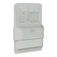
1 - Bring the cell phone closer to the highlighted NFC position, as shown in image (1).
With the cell phone close to it, the controller will beep, signaling that the cell phone has
been detected by the controller.
2 - Keep your cell phone close to initiate communication.
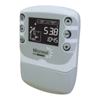
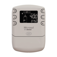
Note: Check the position of the NFC antenna on your cell phone. Using images (2) and
(3) as a reference, it is possible to improve performance by bringing the cell phone
antenna closer to the highlighted position. The correct approximation with the
highlighted NFC position on the controller contributes to an easy and practical use.
Indicates the approach of the smartphone compatible with NFC
technology. At this point, communication between the controller
and the smartphone will be initiated.
Indicates the sending of new parameters to the controller.
Indicates updating of data saved in the controller’s NFC memory.
Important notice: Only the T1, T2 and T3 sensors come with
the product. The T4 sensor can be purchased separately.
Digital input
Configurable dry contact type
PWM / 0-10V output
PWM: 20mA / 500Hz / 10V
AN: 0 - 10V / 10mA
Configurable PWM output for 0 - 10V output
1
2
3
Consumption
5VA
5