Manual defrost:
- To change from “cooling” to “defrost” or vice-versa, irrespective of the programming, hold < key in
for four seconds, until [def]ou [ref] appears in the display.
To visualize the status and the elapsed time, press >.
[del] Initial delay [ref] Refrigeration [def] Defrosting
6. SIGNALLING
REFRIG - Cooling output on
DEFROST - Performing natural defrost
[Err] - Sensor disconnected or temperature out of the specified range.
7. SELECTION OF THE UNIT (Cº / Fº)
In order to define the unit that the instrument will operate in, enter function “F01” with the access code
“231” and confirm with the @ key. Press the < key and the indication [Uni]will appear. Press
@ to choose between [,=C] or [,=F] and confirm. After selecting the unit the [faC] message
will appear, and the instrument will return to the function “F01”. Every time that the unit is changed, the
parameters should be reconfigured, since they assume the “standard” values.
Ver. 09
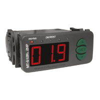
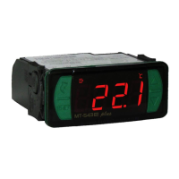
MT-512Ri plus
DIGITAL CONTROLLER FOR COOLING
WITH NATURAL DEFROST THROUGH
COMPRESSOR SHUTDOWN
1. DESCRIPTION
The MT-512Ri plus is a temperature controller and indicator, with a joined cyclical timer. Controls
cooling and defrost through compressor shutdowns. It also has a serial output for communication with
the SITRAD .
Product complies with CE (European Union), and UL Inc. (United States and
Canada).
2. APPLICATIONS
• Counters
• Cooled chambers
3. TECHNICAL SPECIFICATION
- Power supply: MT-512Ri plus 115 or 230 Vac 10%(50/60 Hz)
MT-512RiL plus 12 or 24 Vac/dc
- Control temperature: -50 to 75.0ºC / -58 to 167°F
- Load current: NO 16(8)A/250Vac 1HP
NC 8A/250Vac
- Dimensions: 71 x 28 x 71mm
®
NSF (United States)
±
4. CONFIGURATIONS
4.1 - control temperature adjust (SETPOINT)
- Press @ for 2 seconds until appears [SET] and then release the key.
The set control temperature will appear.
- Use the > and < keys in order to change the value and, when ready, press @ to record.
- Operating temperature: 0 to 50 ºC / 32 to 122°F
- Operating humidity: 10 to 90% RH (without condensation)
CLASSIFICATION ACCORDING TO IEC60730-2-9 STANDARD:
- Temperature limit of the installation surface: 50°C / 122°F
- Type of construction: Built-in electronic controller
- Automatic action: Type 1
- Control of pollution: Level 2
- Impulse voltage: 1,5kV
- Temperature for the test of sphere pressure: 75°C and 125°C / 167°F and 257°F
- Insulation: Class II
4.2 - Parameters table
4.3 - Parameters Alteration
- Access function “F01” by simultaneously pressing keys > and < for 2 seconds.
When the message [FuN]appears release the keys and wait for the[F01] indication. When the
indication appears on the display press the @ key and use > or < to enter the access code
(123) When ready press the @ button to confirm.
- Use keys > or < to access the desired function.
- After selecting the function, press @ (press once quickly) to view the value configured for that
function.
- Use the > or < keys to change the value and, when ready, press @ to memorize the
configured value and return to the function menu.
- To exit the menu and return to the normal operation (temperature indication), press @ (hold it in)
until [---] appears.
5. FUNCTIONS WITH FACILITATED ACCESS
5.1 - Maximum and minimum temperature logs
Press the < key. The minimum and maximum temperatures registered will appear.
Note: To restart the logs you just have to keep the < key pressed during the viewing of the minimum
and maximum temperatures until [rst] to be displayed.
8. WIRING DIAGRAN
Note: The length of the sensor cable may be increased by the user up to 200 meters, using a 2 x 24 AWG
cable. For immersion in water, use thermometric well.
1
2
3
4
5
6
7
8
9
10
11
12
REFRIG
72 mm
29 mm
Dimension of the clipping for
setting of the instrument
in panel
7 - 8
7 - 9
115V
230V
12V
24V
MT-512Ri plus MT-512RiL plus
Power
supply
Load
COMMON
NO
NC
0
Serial communication
RS-485
Load
supply
115 V~
(12 V~)
230 V~
(24 V~)
Sensor
To the terminal of
the distribution box
Above the current specified
use contactor
A
B
9-INTEGRATING CONTROLLERS, RS-485 SERIAL INTERFACE
AND COMPUTER
A
A
B B
A B
A
B
OUT
1
OUT 2
OUT 3
PCT-400R plus
OUT 4
ALMR
A
A
B B
A B
A
B
A
A
B B
A B
A
B
A
A
B B
A B
A
A
B B
A B
PUMP
AUX
1
AUX 2
MICROSOL II plus
Connecting Block for Serial Communication
Used to connect more than one instrument to the Interface. The wire's connections must
be made in agreement with the following rules: terminal A of the instrument connects to
the terminal A of the c , that must be connected with the terminal A of the
Interface. Repeat the action for terminals B and , being the cable shield.
onnecting block
the terminal of distribution box must be connected to the respective terminals of
each instrument.
IMPORTANT
According to the chapters of norm IEC 60364:
1: Install protector against overvoltage on the power supply.
2: Sensor cables and signal cables of the computer may be joined, but not in the same electric conduit
through which the electric input and the activation of the loads run.
3: Install transient suppresors (RC filters) parallel to the loads as to increase the product life of the
relays.
Schematic for the connection of supresors
to contactors
Suppresor
A1
A2
A1 and A2 are the
contactor coil terminals.
Schematic for the connection of supresors to
direct activation loads
Load
Suppresor
For direct activation the maximum
specified current should be taken
into consideration.
Padrão Padrão
Access code: 123 (one hundred and twenty three)
Indication offset
Minimum setpoint allowed for the end user
Maximum setpoint allowed for the end user
Control differential (hysteresis)
Delay to turn the cooling output on
Cooling time
Defrosting time
Initial state up on energizing the instrument
Indication of the temperature locked during defrost
Delay on the activation of the instrument
Additional time at the end of the first cycle
Address of the instrument on the network RS-485
DescripionFun
Min
Max
Unid
-
-5.0
-50
-50
0.1
0
1
0
0 - cooling.
0 - no
0
0
001
-
5.0
75.0
75.0
20.0
999
999
999
1 - defrost
1 - yes
240
240
247
-
°C
°C
°C
°C
sec.
min.
min.
-
-
min.
min.
-
CELSIUS
-
-9
-58
-58
1
0
1
0
0 - cooling.
0 - no
0
0
001
-
9
167
167
40
999
999
999
1 - defrost
1 - yes
240
240
247
-
°F
°F
°F
°F
sec.
min.
min.
-
-
min.
min.
-
FAHRENHEIT
Min
Max
Unid
[F01]
[F02]
[F03]
[F04]
[F05]
[F06]
[F07]
[F08]
[F09]
[F10]
[F11]
[F12]
[F13]
-
00.0
-50
75.0
01.0
020
240
030
0
0
000
000
001
-
000
-58
167
002
020
240
030
0
0
000
000
001
Standard Standard
MT512RIPLV09-04T-11485
REFRIG
MT-512Ri plus
DEFROST
E251415
COMPONENT


 Loading...