8. OPTIONAL ITEMS - Sold Separately
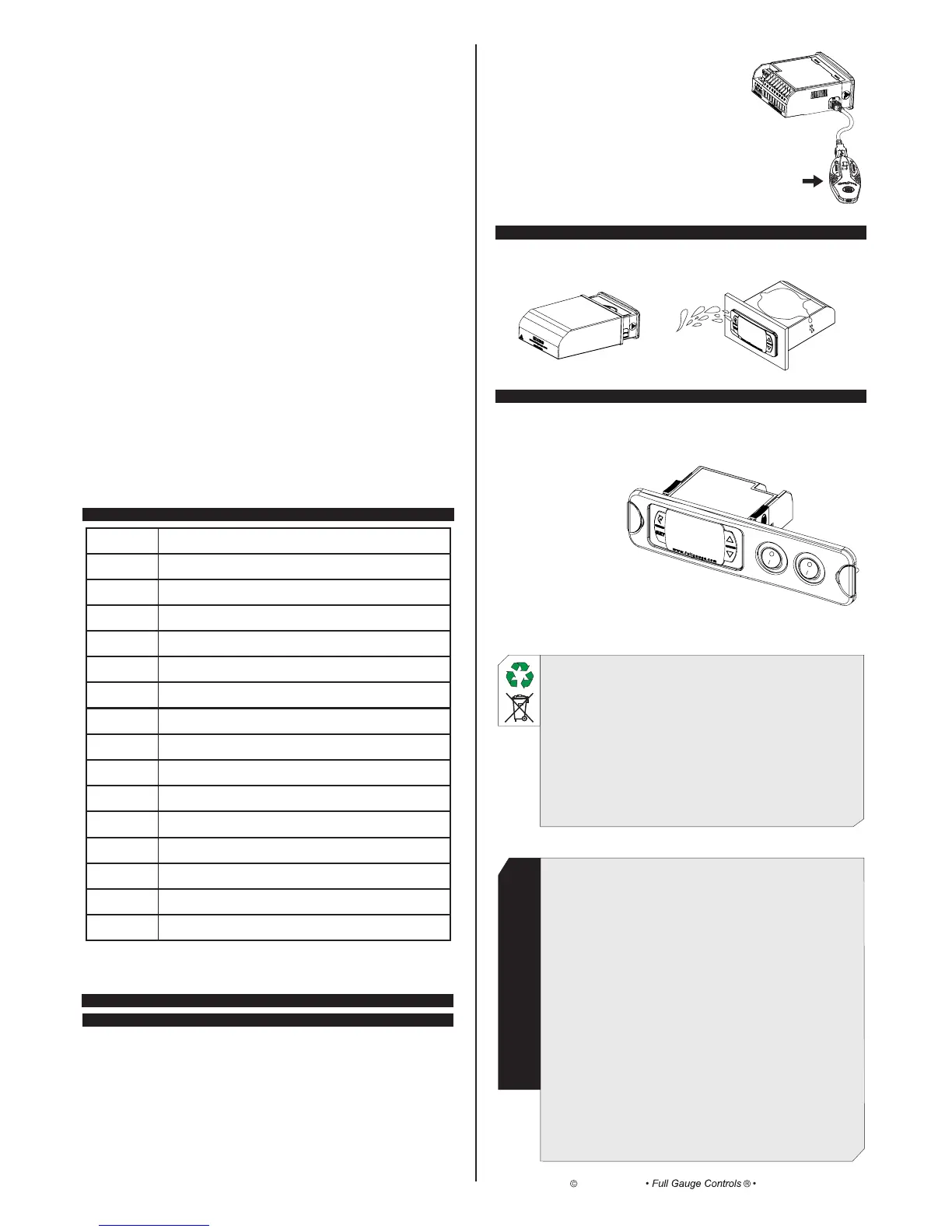
8.1 EasyProg ver. 02
It is an accessory that has as its main function to store the parameters of the controllers. At any time, you
can load new parameters of a controller and unload them on a production line (of the same controller), for
example. It has three types of connections to load or unload the parameters:
- Serial RS-485: It connects via RS-485 network to the controller (only for controllers that have RS-485).
- USB: it can be connected to the computer via the USB port, using Sitrad's Recipe Editor. The parameters
can be copied, edited and saved in EasyProg ver. 02. The USB port can also have the function of
electrically feeding the EasyProg ver. 02 and the controller (when the USB and Serial TTL are
used together).
ENVIRONMENTAL INFORMATION
Packaging:
The materials used in the packaging of Full Gauge products are 100% recyclable. Try to
perform disposal through specialized recyclers.
Product:
The components used in Full Gauge controllers can be recycled and reused if
disassembled by specialized companies.
Disposal:
Do not incinerate or dispose the controllers that have reached the end of their service as
household garbage. Observe the laws in your area regarding disposal of electronic
waste. If in doubt, please contact Full Gauge Controls.
8.2 Ecase
Protective cover for controllers (Evolution line), which prevents the entrance of water and inner moisture. It
protects the product when washing is carried out in the location where the controller is installed.
- Serial TTL: The controller can be connected directly to EasyProg
ver. 02 by the TTL Serial connection. Thus the EasyProg ver.
02 may be fed by , or vice versa. TC-900 e POWER
8.3 Extension Frame
The Full Gauge Controls extension frame allows the installation of Evolution / Ri line with measures
76x34x77 mm (dimensions of the clipping for fixing in the extension frame is 71x29mm) in varied
situations, since it eliminates precision cut to embed the instrument. Allows customization via a sticker with
the brand and the company contact, and accompany two 10A (250 Vac) switches that can trigger internal
light, air curtain, on / off system or fan.
WARRANTY - FULL GAUGE CONTROLS
Products manufactured by Full Gauge Controls, as of May 2005, have a two (02) year
warranty, as of the date of the consigned sale, as stated on the invoice. They are guaranteed
against manufacturing defects that make them unsuitable or inadequate for their intended
use.
EXCEPTIONS TO WARRANTY
The Warranty does not cover expenses incurred for freight and/or insurance when sending
products with signs of defect or faulty functioning to an authorized provider of technical
support services. The following events are not covered either: natural wear and tear of parts;
external damage caused by falls or inadequate packaging of products.
LOSS OF WARRANTY
Products will automatically lose its warranty in the following cases:
- The instructions for assembly and use found in the technical description and installation
procedures in Standard IEC60364 are not obeyed;
- The product is submitted to conditions beyond the limits specified in its technical
description;
- The product is violated or repaired by any person not a member of the technical team
of Full Gauge Controls;
- Damage has been caused by a fall, blow and/or impact, infiltration of water, overload
and/or atmospheric discharge.
USE OF WARRANTY
To make use of the warranty, customers must send the properly packaged product to Full
Gauge Controls together with the invoice or receipt for the corresponding purchase. As much
information as possible in relation to the issue detected must be sent to facilitate analysis,
testing and execution of the service.
These procedures and any maintenance of the product may only be provided by Full
Gauge Controls Technical Support services in the company's headquarters at Rua Júlio de
Castilhos, 250 - CEP 92120-030 - Canoas - Rio Grande do Sul – Brasil
---
EasyProg ver. 02
Copyright 2013
All rights reserved.
Rev. 03
[Err1]
[Err2]
[Err3]
[eCAL]
[ALrE]
[eCO,]
[Opn,]
[AOPn]
[Ahi,]
[Alo,]
[AC1,]
[AC2,]
[ALrC]
[OFF,]
[,,,,.]
[pppp]
7. SIGNALS
Ambient sensor disconnected or out of range.
Evaporator sensor disconnected or out of range.
Sensor 3 disconnected or out of range.
Instrument not calibrated.
External alarm (digital input).
Operating with economic setpoint.
Open door indication.
Open door alarm indication.
High ambient temperature alarm (sensor1).
Low ambient temperature alarm (sensor1).
High temperature in condenser alarm (level 1).
High temperature in condenser alarm (level 2).
Compressor reached the maximum time on without reaching the SP.
Control routines off.
It indicates that the temperature for end of defrost has not been reached.
Loss of parameters.
[,,,6]Digital input: Activate economic setpoint (N.C. push-button)
[,,,7]Digital input: Perform defrost (N.C. push-button)
[,,,8]Digital input: Perform fast freezing (N.C. push-button)
[,,,9]Digital input: External alarm (N.C.)
[,,10]Digital input: Door contact (N.C.)
F51- Ambient temperature S1 indication offset:
This function allows compensating for eventual deviations in the ambient temperature reading (S1),
resulting from the change of sensor or modification of the cable length.
F52 - Evaporator S2 temperature indication offset:
This function allows compensating for eventual deviations in the evaporator temperature reading (S2),
resulting from the change of sensor or modification of the cable length. Sensor S2 can be shut down by
setting this function at minimum until the message [,OFF] appears. In this condition, all functions
dependent on the reading of sensor S2 cease to operate.
F53 - Sensor S3 temperature indication offset:
This function allows compensating for eventual deviations in the reading of sensor S3 temperature,
resulting from the change of sensor or modification of the cable length. Sensor S3 can be shut down by
setting the function of digital input 1 / Sensor S3 (F49) with the [,OFF](0) value, or making it operate
as a digital input.
F54 - Intensity of digital filter applied to sensor 1 (0-deactivated):
This filter is intended to simulate an increase in thermal mass in the sensor thereby increasing its
response time (thermal inertia). The higher the value set in this function, the greater the response time
of the sensor.
F55 - Time for functions lockdown:
It authorizes the locking of the control functions (see section 6.3.7).
[,,,0] - It does not authorize the locking of functions.
[,,15] - [,,60]- It authorizes the locking of functions and sets the time in seconds for the
command to activate.
F56 - Control functions shutdown:
It authorizes the shutdown of the control functions (see section 6.3.8).
[,,,0]It disables the shutdown of the control functions.
[,,,1]It enables to activate/deactivate the control functions only if the functions are unlocked.
[,,,2]It enables to activate/deactivate the control functions even if the functions are locked.
 Loading...