EasyManua.ls Logo

Full Gauge MT-512Ri LOG - User Manual

Full Gauge MT-512Ri LOG
2 pages
Print Icon
To Next Page IconTo Next Page
Loading...
Ver.08
MT-512RiLOG
DIGITAL CONTROLLER FOR COOLING WITH
NATURAL DEFROST THROUGH COMPRESSOR
SHUTDOWN AND INTERNAL DATALOGGER
MT512LOGV08-02T-11157
1. DESCRIPTION
2. APPLICATIONS
3. TECHNICAL SPECIFICATION
The is a temperature controller and indicator, with a joined cyclical timer. Controls
cooling and defrost through compressor shutdowns. It also has an internal datalogger and a serial
output for communication with the SITRAD .
Product complies with CE (European Union) andULInc. (United States and Canada).
Counters
Cooled chambers
MT-512Ri LOG 115or 230 Vac±10%(50/60 Hz)
MT-512RiL LOG 12 or 24 Vac/dc
-50 to 75.0ºC / -58 to 167°F
NO 16(8)A/250Vac 1HP
NC 8A/250Vac
71 x 28 x 71mm
MT-512Ri LOG
®
- Power supply:
- Control temperature:
- Load current:
- Dimensions:
4. CONFIGURATIONS
4.1 - control temperature adjust (SETPOINT)
- Press for 2 seconds until appears and then release the key.
The set control temperature will appear.
- Use the and keys in order to change the value and, whenready,press to record.
- Operating temperature:
- Operating humidity:
0 to 50 ºC / 32 to122°F
10 to 90% RH (without condensation)
SET
SET
4.2 - Parameters table
Description
Fun
Dataloggeroperationmode
Indicationoffset
Minimumsetpointallowedfortheenduser
Maximumsetpointallowedfortheenduser
Controldifferential(hysteresis)
Delaytoturnthecoolingoutputon
Coolingtime
Defrostingtime
Initialstateuponenergizingtheinstrument
Indicationofthetemperaturelockedduringdefrost
Delayontheactivationoftheinstrument
Dataloggersamplinginterval
Variationofthetemperaturetoforcedatarecording
Variationoftheoutputforcedatarecording
Memoryoverwriting
AddressoftheinstrumentonthenetworkRS-485
Additionaltimeattheendofthefirstcycle
Min
Max
Unit
Default
0
-5.0/-9
-50/-58
-50/-58
0.1/1
0
1
0
0-cooling
0-no
0
0
1
0/0
0
001
0-no
2
5.0/9
75.0/167
75.0/167
20.0/40
999
999
999
1-defrost
1-yes
240
240
999
10.0/17
1
247
1-yes
-
°C/°F
sec.
min.
min.
-
-
min.
min.
sec
-
-
-
°C/°F
°C/°F
°C/°F
°C/°F
2
0/0
-50.0/-58
75.0/167
1.0/2
20
240
30
0
0
30
0/0
0
1
0-cooling
0-no
1-yes
8.WIRINGDIAGRAN
Note: The length of the sensor cable may be increased by theuserupto 200 meters, using a 2 x 24 AWG
cable. For immersion in water,usethermometric well.
Power
supply
Load
COMMON
NO
NC
1
2
3
4
5
6
7
8
9
10
11
12
REFRIG
0
72mm
29mm
Serialcommunication
RS-485
Load
supply
Dimensionoftheclippingfor
settingoftheinstrument
inpanel
7-8
7-9
115V
230V
12V
24V
115V~
(12V~)
230V~
(24V~)
MT-512RiLOG
MT-512RiL LOG
Sensor
Totheterminalof
thedistributionbox
Abovethecurrentspecified
usecontactor
A
B
A B
RS-485Network
RS-485 Serial Interface
®
Device used to establish the
connection Full Gauge Controls’
instruments with the Sitrad .
Instrument
RS-485Network
External
mesh
®
IntegratingControllers,RS-485SerialInterfaceandComputer
A
B
PUMP
AUX1
AUX2
MICROSOLIIplus
A
A
B B
A
B
OUT1
OUT2
OUT3
PCT-400R plus
OUT4
ALMR
A
A
B B
A
B
A
A
B B
A
B
A
B
A
B
A
A
B B
A
B
Serialinterface
RS-485
FullGauge
MOD64
A
A
B B
A
B
terminal
grounded
DistributionBox
Used to connect more than one instrumentto the Interface.The wire's connectionsmust
be made in agreement with the following rules: terminal of the instrument connects to
the terminal of the distribution box, that must be connected with the terminal of the
Interface. Repeat the action for terminals and , being the cable shield.
A
A A
B
The terminal of distribution box must beconnected to the respective terminals of
eachinstrument.
4.3 - Parameters Alteration
5. FUNCTIONS WITH FACILITATED ACCESS
5.1 - Maximum and minimum temperature logs
-Access function “F01” by simultaneously pressing keys and for 2 seconds.
When the message appears release the keys and wait for the indication. When the
indication appears on the display press the key and use and to enter the access code
(123) When ready press the button to confirm.
- Use keys and to access the desired function.
- After selecting the function, press (press once quickly) to view the value configured for that
function.
- Use the and keys to change the value and, when ready, press to memorize the
configured value and return to the functionmenu.
- To exit the menu and return to the normal operation (temperature indication), press (hold it in)
until appears.
Press the key.The minimum and maximum temperatures registered will appear.
To restart the logs you just have to keep the key pressed during the viewing of the minimum
and maximum temperatures until to be displayed.
Note:
SET
SET
SET
SET
SET
5.3-Clearingdataloggermemory:
Press the and keys for 4 seconds to display . The display shows . If you
don't want to clear the memory press . To clear the memory press until is displayed and
press to confirm and exit the function.
SET
SET
SET
5.2 - Manual datalogger activation
ou can turn the internal recording ON or OFF by pressing
for seconds The message is displayed followed by the message (datalogger )
and (datalogger ). If the parameter F15 is configured with the values or the
messages or will be displayed accordingly.
Y temperature data (datalogger) or
10 .
5.4-Viewingcurrentdateandtime:
You can press the key shortly to view the date and time set in the controller. The display shows the
current day,month, year, hoursand minutes, in this order:
Ex: 03/17/2006 12h43min
SET
Hours
Day
Month
Year
5.5 - Manual defrost:
6. SIGNALLING
7. SELECTION OF THE UNIT (Cº / Fº)
- To change from “cooling” to “defrost” or vice-versa, irrespective of the programming, hold key in
for four seconds, until or appears in the display.
To visualize the status and the elapsed time, press .
Initial delay Refrigeration Defrosting
- Cooling output on
- Performing natural defrost
- Sensor disconnectedor temperature out of the specified range.
In order to define the unit that the instrument will operate in, enter function “F01” with the access code
“231” and confirm with the key. Press the key and the indication will appear. Press
to choose between or and confirm.After selecting the unit the message will
appear, and the instrument will return to the function “F01”. Every time that the unit is changed, the
parameters should be reconfigured, since they assumethe “standard” values.
REFRIG
DEFROST
SET
SET
Question and Answer IconNeed help?

Do you have a question about the Full Gauge MT-512Ri LOG and is the answer not in the manual?

Summary

Description and Applications

Product Description

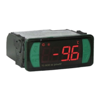
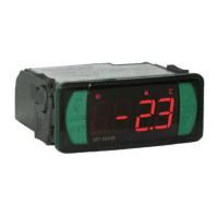
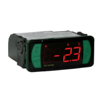
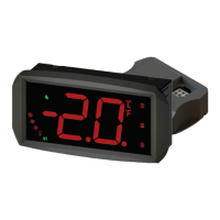
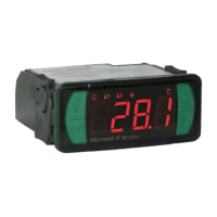
Provides a general description of the MT-512R® LOG controller.

Applications

Details the intended uses and applications for the controller.

Technical Specifications and Configurations

Technical Specifications

Lists the electrical and physical specifications of the controller.

Control Temperature Adjustment

Allows setting the control temperature (Setpoint) for the device.

Parameters Table

Presents a table detailing various operational parameters.

Functions with Facilitated Access

Maximum and Minimum Temperature Logs

Allows viewing the recorded maximum and minimum temperature logs.

Manual Datalogger Activation

Enables manual activation of the datalogger function.

Clearing Datalogger Memory

Provides instructions for clearing the datalogger's stored memory.

Viewing Current Date and Time

Explains how to view the controller's current date and time settings.

Manual Defrost

Details the process for manually initiating a defrost cycle.

Signalling Configuration

Covers the configuration of signalling and output settings.

Unit Selection (°C; °F)

Allows the user to select the preferred temperature unit (°C or °F).

Wiring Diagram and Important Notes

Wiring Diagram

Illustrates the electrical wiring connections for the controller.

Important Installation Notes

Provides crucial guidelines for safe and correct electrical installation.

Protective Vinyl Application

Instructions for applying the protective vinyl for water resistance.

Overview

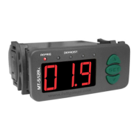
The MT-512Ri LOG is a versatile digital controller designed for managing cooling systems that utilize natural defrost through compressor shutdowns. It also features an integrated datalogger and a serial output for communication with the Sitrad® software, making it suitable for applications such as counters and cooled chambers.

Function Description

The primary function of the MT-512Ri LOG is to control and indicate temperature. Users can easily adjust the control temperature (setpoint) by pressing the SET key for two seconds, releasing it when "SET" appears, and then using the UP and DOWN keys to change the value. The new setpoint is recorded by pressing SET again.

The device offers a comprehensive set of configurable parameters to fine-tune its operation. These include the datalogger operation mode, indication offset, minimum and maximum setpoints allowed for the end user, control differential (hysteresis), and delays for turning the cooling output on. Users can also configure cooling time, defrosting time, the initial state upon energizing the instrument (cooling or defrost), and additional time at the end of the first cycle. For datalogging, parameters such as the sampling interval, temperature variation to force data recording, and output force data recording can be set. The device also supports memory overwriting and allows for the configuration of its address on an RS-485 network.

To alter these parameters, users access function "F01" by simultaneously pressing the UP and DOWN keys for two seconds. After "Fun" appears, the keys are released, and "F01" is displayed. Pressing SET and entering the access code (123) confirms entry. Users can then navigate through functions using the UP and DOWN keys. To view a configured value, press SET quickly. Values can be changed using the UP and DOWN keys and saved by pressing SET. To exit the menu and return to normal temperature indication, press and hold SET until "SET" appears.

Usage Features

The MT-512Ri LOG provides several features for convenient operation and monitoring.

Temperature Logging: Users can view the minimum and maximum temperatures recorded by pressing the UP key. To reset these logs, the UP key must be held until "SET" is displayed.

Manual Datalogger Activation: The internal temperature data recording can be manually turned ON or OFF by pressing the UP or DOWN key for 10 seconds. The display will show "LOG" followed by "ON" or "OFF" depending on the status.

Clearing Datalogger Memory: The datalogger memory can be cleared by pressing the SET and DOWN keys simultaneously for four seconds. "DEL" will appear, followed by "NO." To confirm clearing, press the UP key until "YES" is displayed, then press SET.

Viewing Current Date and Time: A short press of the SET key allows users to view the current date and time configured in the controller. The display cycles through day, month, year, hours, and minutes.

Manual Defrost: To manually switch between cooling and defrost, regardless of the programmed cycle, users can hold the DOWN key for four seconds until "DEF" or "REF" appears. The status and elapsed time can be viewed by pressing the DEL key.

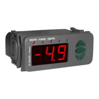
Signaling: The device uses clear indicators for its operational status:

  • REFRIG: Indicates that the cooling output is active.
  • DEFROST: Indicates that natural defrost is in progress.
  • Err: Signals a disconnected sensor or a temperature outside the specified range.

Unit Selection: The operating unit (Celsius or Fahrenheit) can be selected by entering function "F01" with access code "231." Pressing SET, then UP, will display "C" or "F." Users can choose the desired unit by pressing SET. After selection, "FAD" will appear, and the instrument will return to "F01." It's important to note that changing the unit will reset parameters to their standard values, requiring reconfiguration.

Maintenance Features

To ensure the longevity and proper functioning of the MT-512Ri LOG, several installation and maintenance guidelines are provided.

Wiring Diagram: The manual includes a detailed wiring diagram for connecting the power supply, sensor, and load. It specifies connections for 115V-230V~ or 12V-24V- power supplies and outlines the terminals for serial communication (RS-485).

Sensor Cable Length: The sensor cable length can be extended up to 200 meters using a 2 x 24 AWG cable. For applications requiring immersion in water, a thermometric well is recommended.

Integrating Controllers: The device is designed to integrate with other controllers, an RS-485 serial interface, and a computer via the Sitrad® software. A distribution box is used to connect multiple instruments to the interface, with specific wiring rules for terminals A, B, and the cable shield.

Important Installation Guidelines:

  • Overvoltage Protection: Install a protector against overvoltage on the power supply.
  • Cable Routing: Sensor and signal cables should not be run in the same electric conduit as the input power and load activation cables.
  • Transient Suppressors: Install transient suppressors (RC filters) parallel to the loads to increase the lifespan of the relays. Schematic diagrams are provided for connecting suppressors to contactors and direct activation loads.

Protective Vinyl: An adhesive vinyl is included in the packaging to protect the instrument from water drippings, common in commercial refrigerators. This vinyl should be applied after completing all electrical connections, covering the superior part of the device and folding the flaps as indicated.

Full Gauge MT-512Ri LOG Specifications

General IconGeneral
ModelMT-512Ri LOG
TypeTemperature Controller
ManufacturerFull Gauge
Resolution0.1 °C
Dimensions71 x 28 x 71 mm
ProtocolModbus RTU
Data LoggingYes
Temperature Range-50 to 105 °C
Operating Temperature0 to 50 °C
Measurement Temperature-50 to 105 °C
CommunicationRS485
Humidity10 to 90% RH (non-condensing)
Protection ClassIP65

Related product manuals