6/8
CLICK !!
push
drücken
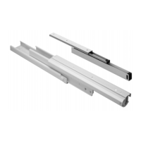
+ Auszugmodul einsetzen und lt.
Einbauzeichnung 5a/b und 6a/b bis zum
Anschlag aufschieben.
Während des Einschiebens rastet der
obere Anschlag drei mal ein und drei
deutliche „Clicks“ sollten zu hören sein (Fig. A).
Der untere Adapter muss in die Haken der
Führung einrasten.
+ Insert the pull-out as shown in drawing 5a/b
and 6a/b and push it to the end stop.
While sliding-in, the stop piece at the top snaps
in three times and it should “Click” three times
(Fig. A). The adapter at the bottom should
click into the black hooks on the slide.
L
R
L
R
7
B
C
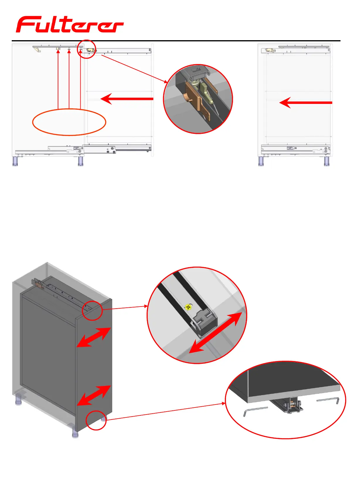
+ Die Seitenverstellung an der Gegenführung
lt. Einbauzeichnung 7 erfolgt über ein
im U-Profil angebrachtes Langloch (Fig. B).
+ Use the slotted holes in the U-profile of the
top guide to make the upper lateral
adjustment of the pull-out as shown in
drawing 8 and Figure. B.
+ Inbusschrauben für die Adapter-Fixierung
(Fig. C) vorsichtig bis zum Anschlag eindrehen.
+ Die Seitenverstellung an der Bodenführung
lt. Einbauzeichnung 7 erfolgt über das
Verdrehen der linken und rechten
Inbusschraube (Fig. C) im Bereich ±2mm
+ Close Allen screws carefully to secure the
adapter (Fig. C).
+ Use the Allen screws in the bottom slide
as shown in drawing 7 for the lateral
adjustment of the pull-out (Fig. C).
6a
6b
A