as keeping signal levels high to minimize hum and
noise, and ease of access to all foot switches. The
Velcro system of attachment allows pedals to be
repositioned if necessary. Individual pedals should
be connected in a signal chain using short patch
cords (not supplied). The input to the rst pedal
should be patched to the To Pedal (Input) jack on
the SPB-8/E; the output of the last pedal should be
patched to either of the From Pedals jacks (both
should be used if the pedal has a stereo output). See
the next section for more on the SPB-8/E’s patching
capabilities.
3. Provide Power: The SPB-8/E can power
almost any pedal made, using one of its four power
options. Three of these provide 9 VDC power, and
the fourth is 120 VAC “wall” power (E Version 230
VAC Wall outlet).
9 VDC Power is typically used in pedals that can
run off batteries, or off battery eliminators. The SPB-
8/E provides eight 9 VDC power outlets, all of which
use 3.5 mm “miniplug” connectors on the pedal board
end. On the pedals themselves, several connector
types may be used, the most common of which is
called “P205L” or “DC connector”. This may easily be
recognized as a 5 mm round hole (often in a block of
black plastic insulating material), with a single metal
pin in the center. Eight miniplug-to-DC cables are
provided with the SPB-8/E. Some 9V pedals use a
miniplug connector instead of a DC connector. One
miniplug-to-miniplug cable is provided with the SPB-
8/E for such pedals. Finally, a few pedals have no
provision for any form of power other than batteries.
Should you encounter one of these, one miniplug-to-
battery-clip cable is also provided. To use it, simply
remove the battery and connect the pedal’s battery
clip to the one on the cable.
Each of the SPB-8/E’s DC power outputs is
individually fused and protected against shorts, so
pedals can be plugged in without risk even while the
pedal board is powered up. Each output can supply
up to 100 mA, which should be adequate for virtu-
ally any pedal. Because the SPB-8/E is protected
by Furman’s famous power conditioning capability,
your valuable pedals will be protected from damage
from spikes and surges.
120 VAC Power may be needed for a few pedals.
Three grounded, 15A outlets are provided. These
may also be used for non-pedal effects, such as
those mounted in racks.
4. Packing up: Once all pedals have been po-
sitioned, linked in a signal chain, and powered, the
SPB-8/E is ready for use on stage. After use, the
entire unit with pedals and all cabling attached may
be slipped into its padded Cordura case and trans-
ported. An internal strap holds the pedal board in
place. The case has both a handle and a detachable
shoulder strap for easy carrying. There are also two
internal zippered pouches for cables and other ac-
cessory items.
Sample Hookups
The SPB-8/E offers very exible patching op-
tions that will allow easy connection of mono and/or
stereo pedal effects, rack effects, and instruments
and amps. Several examples are presented here to
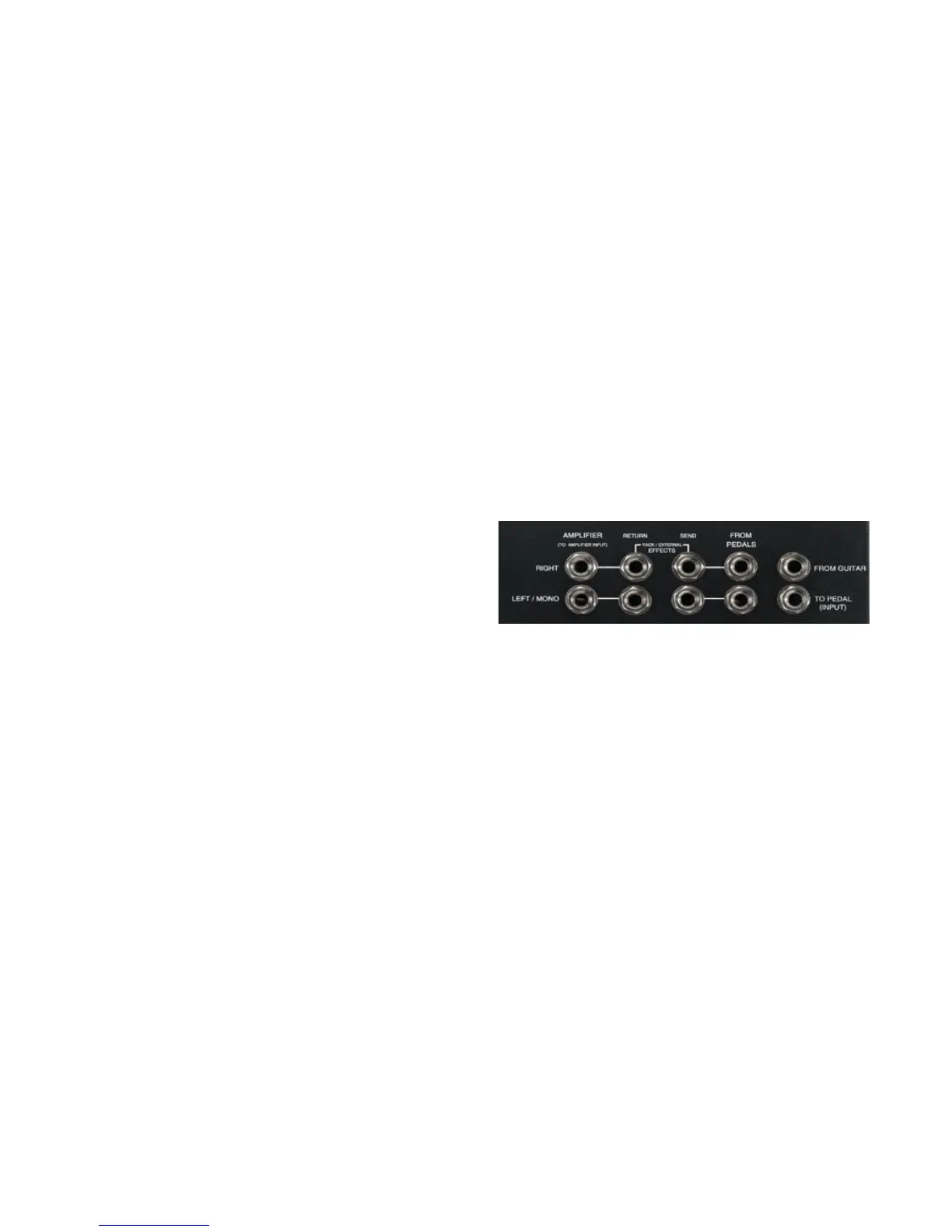
illustrate its capabilities. To understand the patch bay,
consider the “normal” signal ow through it, indicated
by the dotted lines with arrows showing direction:
Note that there are two channels, Left/Mono and
Right. If nothing is plugged into the switching jacks
(marked “S”), signal will ow unimpeded from the rst
jack (From Guitar, for Left/Mono, or From Pedals,
for Right) to the last jack (Amplier, for both Left/
Mono and Right) in each channel. Each of the three
jacks marked “U” is unswitched and may be used to
take a “tap” off the signal path without breaking it,
provided the jack to its immediate left is unused.
All hookups begin by connecting the guitar or
other instrument into the From Guitar jack, and the
input to the rst pedal in the pedal chain to the To
Pedal (Input) jack. From there, the exact hookup
used depends on whether the pedals have mono or
stereo outputs, whether rack effects as well as pedals
are used, and whether one or two amps are used.
 Loading...