17
Set the jumper pins referring to the below table to set the logical setting of contact signals and
terminating resistors.
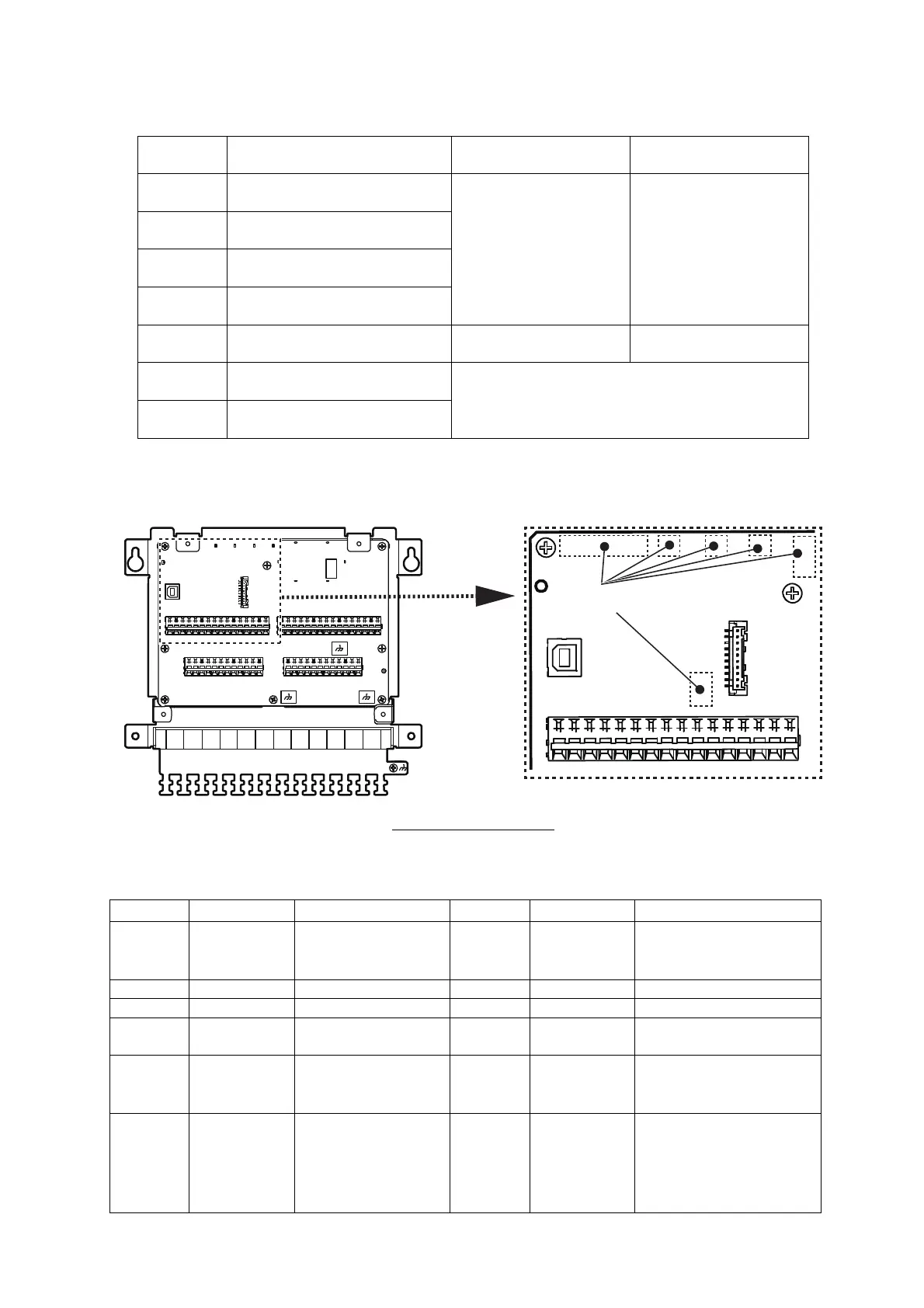
10. LED INDICATIONS
The location of the LED
After the wiring, check the LED indications referring to the next table to check the condition of signals.
In the normal condition, LED blinks as follows:
Jumper No. Function
1-2
Short
2-3
Short
JP1 The logical setting of ALARM 1
(Contact Signal)
Normal Close Normal Open
JP2 The logical setting of ALARM 2
(Contact Signal)
JP3 The logical setting of ALARM 3
(Contact Signal)
JP4 The logical setting of ALARM 4
(Contact Signal)
JP5* The setting of the terminating
resistor for IN1
The terminal resistors are
set
The terminal resistors are
not set
JP6* The setting of the terminating
resistor for IN2
*
: JP5, JP6 and JP7 is only on the board of IF-2550-
IEC2.
JP7* The setting of the terminating
resistor for IN3
LED Color Function LED Color Function
CR1 Yellow-green Debugging CPU CR11 Yellow-green Blinks when data is
transmitted to output ports
OUT9.
CR2 Red Error notification 1 CR12 Yellow-green Transmitting baud rate.
CR3 Red Error notification 2 CR13 Yellow-green Receiving baud rate.
CR4 Red Error notification 3 CR14 Yellow-green Lights when the power is
on.
CR5 Red Error notification 4 CR15 Yellow-green Check the selected port in
IF-2500 mode 1.
CR6 Yellow-green Blinks when data is
received at the input
port IN1.
CR16 Yellow-green Check the selected port in
IF-2500 mode 2.
 Loading...