and gently pull rearwards.
gently snap into position.
Switch/Knob Airplane (ACRO) Sailplane/Glider (GLID) Helicopter (HELI)
A or H Tx.
SWITCH A elevator dual rate elevator dual rate elevator dual rate
down = butterfly on
Switch B rudder dual rate rudder dual rate rudder dual rate
Switch C up = ELE-FLP on up = ELE-FLP on governor/ch 7
center/down = IDLE-DOWN center/down = IDLE-DOWN
down = AIRBRAKE on
S
WITCH D aileron dual rate aileron dual rate aileron dual rate
Switch E
OR G* landing gear/ch 5 GLID1FLP = gear throttle hold
Switch F
OF H* snap roll/trainer trainer trainer/THR-CUT
SWITCH G OR E* none back = SPEED OFFSET idle-up 1 and 2
fwd = START OFFSET
SWITCH H OR F* none none idle-up3/ch 5/gyro
K
NOB A flap/ch 6 GLID1FLP: flap HOVERING PITCH
(flap trim if FLAPERON on) (flap trim if FLAPERON on)
GLID2FLP: camber
(flap trim if FL-AIL off)
K
NOB B ch 8 ch 8 ch 8
K
NOB C spoiler/ch 7 spoiler/ch 7 HOVERING THROTTLE
(disabled if AIL-DIFF on) (disabled if AIL-DIF on)
S
LIDER D none GLID1FLP: ch 5 none
S
LIDER E none none none
*On the 9CH transmitters, the TOP LEFT SWITCHES are spring-loaded and 3-position; on the 9CA, those switches are on the right side. For consistency,
the switch position’s designation remains the same (upper left is F, etc), but the functions are moved to match the switch type.
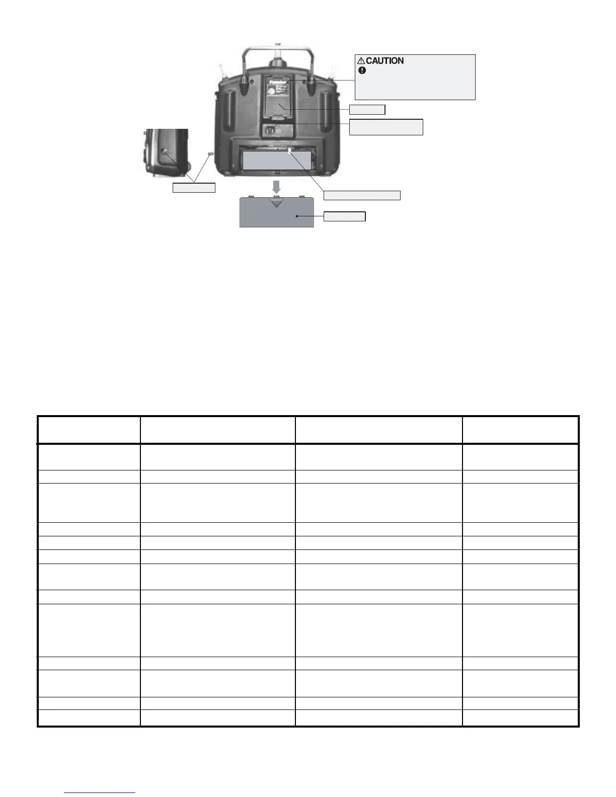
NOTE: If you need to remove or replace the transmitter battery, do not pull on its wires to remove it. Instead,
gently pull on the connector's plastic housing where it plugs into the transmitter.
SWITCH ASSIGNMENT TABLE
•
The factory default functions activated by the switches and knobs for a Mode 2 transmitter are shown below.
•
Most 9C functions may be reassigned to non-default positions quickly and easily.
•
Basic control assignments of channels 5-9 are quickly adjustable in AUX-CH (see pp. 39). For example, the channel 5
servo, which defaults to SWITCH E for retract use, can easily be unassigned (NULL) to allow for easy use as a second
rudder servo in a mix, or to a slider or dial for bomb door or other control.
•
Note that most functions need to be activated in the programming to operate.
•
Mode 1 transmitter functions are similar but reverse certain switch commands. Always check that you have the desired
switch assignment for each function during set up.