- 1 -- 4 -
Important: The AdRCSS 900MHz band offers different
characteristics than that of the conventional 50MHz, 72MHz
and 2.4GHz. As such, we strongly encourage you to read
this manual carefully prior to utilizing the TM-18 RF and
R9001SB system.
1M23N39005
TM-18 RF Module/R9001SB ReceiverTM-18 RF Module/R9001SB Receiver
TM-18 RF Module
Specications:
TM-18 RF Module
● Communicationsystem:one-waycommunication
● CompatiblewithallFutabasystems
(FASTTest,FASSTMULTI/7CH,S-FHSS,T-FHSS)
Two-waycommunication(telemetry)isnotsupported.
● Currentconsumption:36mAmaximum
● SettingswitchforLINKandrangecheck
[R9001SB Receiver]
● Dualantennadiversity
● Powerrequirement:4.8V-7.4VDrybatteriescannotbeused
● FailSafe(F/S)function(forthrottlechannel)
● Size:1.48x0.83x0.21in (37.5x21.1x5.3mm)
● Weight:0.16oz.(4.6g)
*Besure thatwhen usingESC's regulatedoutput thecapacity ofthe
ESCmustmeetyourusagecondition.Neverusedrycellbatteriesfor
theR9001SBreceiveras this maycausediculties with the receiver's
operation.
*The amount of maximum channelsfor S.BUS/S.BUS2output depends
onthetransmitter.(UnusedCHwillbeneutraloutput.)Also,atF/S,the
F/SsettingCHwillbeattheF/Sposition,andotherthanthatwillbein
theHoldstate.
AdRCSS 900MHz System
TM-18 RF Module
and
R9001SB Receiver
Thank you for purchasing the AdRCSS 900MHz system TM-Thank you for purchasing the AdRCSS 900MHz system TM-
18 RF transmitter module and R9001SB receiver. This system is 18 RF transmitter module and R9001SB receiver. This system is
available only with the Futaba transmitters listed left side in this page. available only with the Futaba transmitters listed left side in this page.
The receiver R9001SB is capable of controlling models up to 16 The receiver R9001SB is capable of controlling models up to 16
channels. Please install the R9001SB carefully according to the manual.channels. Please install the R9001SB carefully according to the manual.
* AdRCSS stands for Advanced Radio Control System for Sub-GHz band. * AdRCSS stands for Advanced Radio Control System for Sub-GHz band.
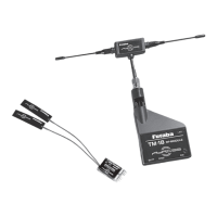
Shows Futaba 900MHz products.Shows Futaba 900MHz products.
Applicable systems:
T16IZ, T16IZS, T18SZ, T32MZ
(Nodedicatedpowersupplyrequired)
T12K, T16SZ (Requiresdedicatedpowersupply)
R9001SB Receiver
CRSF signal connection cable
Instruction Manual
Usage Precautions:Usage Precautions:
WARNING
Beforeutilizinganyradiocontrolsystem,itisstrongly
recommendedthatyoureadandabidebytheSafetyCodecreated
bytheAcademyofModelAeronauticsandanysite-specificrules
andregulationsthatmightexist.Doingsowillsignificantlyincrease
yourenjoymentofthehobby.
Tomaintaincompletecontrolofyouraircraft,itmustalways
remainvisible.Flyingbehindlargeobjects,suchasbuildings,grain
bins,etc.,isnotsuggested.Doingsomayresultinthereductionof
thequalityoftheradiofrequencylinkedtothemodel.
Pleasedonotgraspthetransmittermodule'santennaduring
flight,anddoingsomaydegradethequalityoftheradiofrequency
transmission.
Ifthere'reanynoiseorotherRFdevicesatsame900MHzband,
thelinkofAdRCSSmightbedegraded.Alwayscheckyourcontrol
isbeingkeptandifanysymptomoflossofcontrolfeltpleasestop
usingimmediately.
Donotallowothertransmitters,mobilephones,orwireless
devicestocontactorcomeclosetotheTM-18during
operation.Doingsomaycausemalfunction.
Donotpointthetipoftheantennatowardtheaircraftduring
flight.(Radiowavesaremaximizedinthelateraldirectionofthe
antenna.)
WARNING
DonotpressthetactSWduringtheflightasthemodulewillbe
inrangecheckmodesothattheRFpowerwillbeloweredandwill
resultinfatalcrash.
©Copyright 2023. No part of this manual may be reproduced in any form without prior permission. The contents of this manual are subject to change without prior
notice. While this manual has been carefully written, there may be inadvertent errors or omissions. Please contact our service center if you feel that any corrections or
clarications should be made. Futaba is not responsible for the use of this product.
FUTABA CORPORATION
Hobby Radio Control Business Center Sales & Marketing Department 1080 Yabutsuka, Chosei-mura, Chosei-gun, Chiba-ken, 299-4395, Japan
TEL: +81-475-32-6051, FAX: +81-475-32-2915
©FUTABACORPORATION2023,12(2)
Features
• Exclusive ID code to avoid interference from other AdRCSS • Exclusive ID code to avoid interference from other AdRCSS
900MHz systems.900MHz systems.
• Fail Safe (F/S) function (for throttle channel)• Fail Safe (F/S) function (for throttle channel)
Recommendation
• It is recommended to use Futaba AdRCSS 900MHz system and • It is recommended to use Futaba AdRCSS 900MHz system and
Futaba 2.4GHz system at the same time using Dual RX Link Futaba 2.4GHz system at the same time using Dual RX Link
System receiver (main = 2.4GHz system)System receiver (main = 2.4GHz system)
●Tact SW of R9001SB●Tact SW of R9001SB
UsedforS.BUSmodechangeandF/Ssetting.
●Tact switch of TM-18 RF module●Tact switch of TM-18 RF module
Usedforlinkingwiththereceiverandapower-downmode.
ConnecttransmitterandTM-18
Conrmation of F/S operation
AfterswitchingHOLD
CH3-F/Smode,checkthefail-safeoperationby
followingtheprocedurebelow.
1
Gas-powered models with the engine stopped. For electric airplanes,
thepropellerisremovedfromthemotor.Forelectrichelicopters,the
piniongearisremovedfromthepowermotortoensurethattherotordoes
notrotate.
2
Turnonthetransmitterandreceiver.
3
Waitatleast5secondsafterturningonthetransmitterorlinking.
4
Turnoonlythetransmitter.
5
Forgas-poweredmodels,checkwhetherthethrottleservoreachesthe
setslowposition;forelectricmodels,checkwhetherthemotorstops.
WARNING
WhensettingandcheckingtheoperationoftheF/S,stoptheengine
forgasolinemodelsandkeepthepropellersandrotorsfromrotatingfor
electricmodels.Suddenrotationofpropellersandrotorsmaycauseinjury.
Range Check the RadioRange Check the Radio
Forsafeuse,alwaysperformadistancetestbeforeying.TheTM-18hasa
power-downmode(lowpowermode)dedicatedtodistancetesting.
Thedistancetestmethodbelowisforthecasewherethe2.4GHzDualRX
Linksystemreceiveronpage3isconnectedasanexample.
AlternatelytestboththeFutaba AdRCSS 900MHzsystemandtheFutaba
2.4GHzsystem.
1
TurnonthetransmitterandreceiverandensurethatboththeFutaba
AdRCSS 900MHzandtheFutaba 2.4GHzsystemsareworking
correctly.
2
<Futaba AdRCSS 900MHz system distance test>
Keepthereceiver side ON, turn the transmitter OFF once, andturn
thetransmitterONagainwithoutoutputting2.4GHz radiowaves.Pressthe
tact switchof TM-18 forabout 10 seconds. TheLEDwill flashred/green
simultaneouslyandwillbetransmittedinapower-downmodeforabout90
seconds.TheLEDreturnstosolidgreen.(2.4GHziso,and900MHzisinthe
power-downmode)
*Forinformationonhowtoturnonthepowerwithoutemittingradiowaves,
please refer to the instruction manual section "Settings without emitting
radio waves"sectionforeachtransmitter.FortheT12K,turnonthe
transmitterpowerwhilepressingRTN, and select "RFOFF"onthepower
modeswitchingscreen.
* Pleasenotethatifyouturnonthetransmitterwhilepressingthetact switch
ofTM-18,noradiowaveswillnoemitfromTM-18.
*IfyoupressthetactswitchofTM-18againwhilethepower-downmodeis
running,thepower-downmodewillbeextendedforabout90seconds.
3
Moveawayfromtheplanewhileoperatingthestickinapower-down
mode.Moveawayfromthemodelwhileusingthestickinthepower-
downmode.Haveyourassistantcheckthatallcontrolsareworkingcorrectly
atadistanceofabout30-50stepsfromtheplane.
4
At this time, if the servo moves dierently from the operation, there
maybesomeproblems.Donotflyuntilthecauseiseliminated.
Inaddition,checktheloosenessoftheservoconnectionandthelinkage
condition.Also,useafullychargedbattery.
5
<Futaba 2.4GHz system distance test>
Turnoffthetransmitter's powerwhileleavingthereceiver's
poweron.
6
WhilepressingthetactswitchofTM-18,pleaseturnonthetransmitter
andmakeitinastatewherethe 900MHz radiowaveisnotemitted.
Setthetransmittertorangecheckmode.Doadistancetestaswellas
900MHz.(Only2.4GHzradiowavesareemitted)
7
Aftercompletingthedistancetest,pleaseturnoffthe
transmitterandturnitonasusual.(Both2.4GHzand
900MHzareON)
WARNING
Distancetestwithengineoffforgas-poweredmodels.For
electricairplanes,removethepropellerfromthepowermotor.For
electrichelicopters,dragthepiniongearfromthepowermotorso
thattherotordoesnotrotate.
Other PrecautionsOther Precautions
TheTM-18 antennaisfixedwithscrews1,2,and3,shown
below.Ifthesepartscomeloose,youmaylosecontrolandcrash.
Checkforloosenessbeforeturningonthetransmitter.
WhenusingatransmitterequippedwithTM-18ontheteacher
sideofthetrainerfunction,donotswitchthetrainerswitchafter
turningonthetransmitterandbeforethereceiversidebecomes
operable.Doingsomaycausemalfunction.
*WhenusingtheTM-18withtheT12K,thetrainer cablecannotbe
connected,sothetrainerfunctioncannotbeused.
Tact SWTact SW
Tact SWTact SW
BATT portBATT port
CRSF PortCRSF Port
LEDLED
LEDLED
Connectadedicatedpower
supply(4.8V to7.4V) when using
theT12KandT16SZ.
PortforinsertingCRSF
signalconnectioncable.
For safety’s sake, pay special attention whenever you see the marks shown here.
Symbol Explanationk
DANGER
Indicatesa procedurewhich couldleadto adangerous situation
andmaycausedeathorseriousinjuryifignoredandnotperformed
properly
WARNING
Indicatesprocedureswhichmay leadtodangeroussituationsand
couldcausedeathorseriousinjuryaswellassupercialinjuryand
physicaldamage.
CAUTION
Indicatesprocedures thatmay notcauseserious injury,but couldlead
tophysicaldamage.
[Symbol] ; Prohibited ; Mandatory
Percentage of Waste
Paper pulp 80%
Compliance Information Statement (for U.S.A.)
This device, trade name Futaba Corporation, model number R9001SB, complies with part15 of the FCC
Rules. Operation is subject to the following two conditions:
(1) This device may not cause harmful interference, and
(2) This device must accept any interference received, including interference that may cause undesired operation.
CAUTION: To assure continued FCC compliance
1. Any changes or modications not expressly approved by the grantee of this device could void the user's
authority to operate the equipment.
2. This equipment complies with FCC radiation exposure limits set forth for an uncontrolled environment.
This transmitter must not be co-located or operating in conjunction with any other antenna or transmitter.
This equipment complies with FCC radiation exposure limits set forth for an uncontrolled environment. This
equipment should be installed and operated with minimum distance 20cm between the radiator & your body.
The responsible party of this device compliance is:
FUTABA Corporation of America 2681 Wall Triana Hwy Huntsville, AL 35824, U.S.A.
Phone:1-256-461-9399 FAX:1-256-461-1059 E-mail: service@futabaUSA.com
Compliance Information Statement (for Canada)
This device complies with Industry Canada license-exempt RSS standard(s). Operation is subject to the fol-
lowing two conditions: (1) this device may not cause interference, and (2) Cet équipement est conforme aux
limites d'exposition au rayonnement du CI établies pour un environnement non contrôlé. Cet émetteur ne doit
pas être co-situé ou fonctionner conjointement avec une autre antenne ou émetteur.
Cet équipement est conforme aux limites d’exposition aux rayonnements IC établies pour un environnement
non contrôlé. Cet équipement doit être installé et utilisé avec un minimum de 20 cm de distance entre la
source de rayonnement et votre corps.
French: Cet appareil radio est conforme au CNR-210 d’Industrie Canada. L’utilisation de ce dispositifest
autorisée seulement aux deux conditions suivantes : (1) il ne doit pas produire de brouillage, et (2) l’utilisateur
du dispositif doit être prêt à accepter tout brouillage radioélectrique reçu, même sice brouillage est suscep-
tible de compromettre le fonctionnement du dispositif. Cet équipement est conforme aux limites d’exposition
aux rayonnements IC établies pour un environnement non contrôlé.
Cet équipement est conforme aux limites d’exposition aux rayonnements IC établies pour un environnement
non contrôlé. Cet équipement doit être installé et utilisé avec un minimum de 20 cm de distance entre la
source de rayonnement et votre corps
.
11
22 33
This radio transmitter (FCC ID: AZPTM18, IC: 2914D-TM18) has been approved by Federal
Communications Commission or Innvoation, Science and Economic Development Canada
to operate with the antenna types listed below with the maximum permissible gain indicated.
Antenna types not included in this list, having a gain greater than the maximum gain indicated
for any type listed are strictly prohibited for use with this device.
No. Antenna Type Model Name Gain(Peak)
1. 1/2 λ di-pole type 9M99Z11701 3.83 dBi