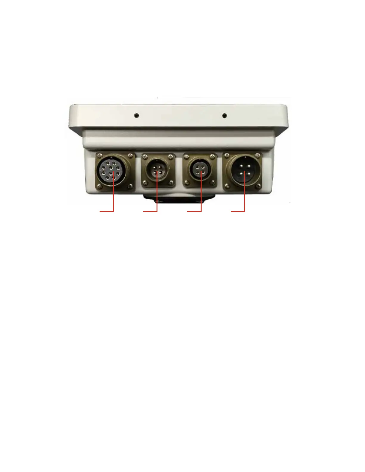
4. Power Cable Connector - Battery power is routed to the system via this cable connection.
Page 4
7) Left LED Grade Display -
8) Right LED Grade Display - These LED’s display whether you are above grade, below grade or
on grade. The red arrows tell the user which direction the blade must move to achieve grade, while
the single up or down red LED will ash when the receiver is within 10mm (0.39”) of the desired
grade. The green LED’s in the middle will ash when you are within your desired ‘on grade’.
12. Power On/Off switch - Press the power button briey to turn it on, and the button must be
pushed and held for approximately two seconds to turn the system off. This button is also used as a
soft key providing the function indicated in the display directly above it.
1. Valve Cable Connector - This is where the valve cable is connected to the control box.
2. Remote Switch Connector - The remote auto/raise/lower toggle switch assembly plugs into the
control box via this connector.
3. Communication Connector - Receiver and Sensors plug into the Node Box, their signals are tras-
fered to the control box via this 4 pin connector.
1. 2. 3. 4.
 Loading...