5 of 13
2.3 Wiring
Electrical power in an industrial environment contains a certain amount of noise in the form of
transient voltage and spikes. This electrical noise can enter and adversely affect the operation
of microprocessor-based controls. For this reason, we strongly recommend the use of shielded
thermocouple extension wire which connects the sensor to the controller. This wire is of
twisted-pair construction with foil wrap and drain wire. The drain wire is to be attached to
ground at one end only.
The utmost care must be taken to ensure that the maximum voltage rating specified on the
controller label is not exceeded. It is recommended that the supply power of these units be
protected by a fuse or circuit breaker rated at the lowest value possible.
All units should be installed inside a suitably grounded metal enclosure to prevent live parts
being accessible to human hands and metal tools.
All wiring must conform to appropriate standards of good practice and local codes and
regulations. Wiring must be suitable for the voltage, current and temperature rating of the
equipment.
The tightening torque on the screw terminals should not exceed 1 N-m (8.9 Lb-in or 10.2 Kg F-
cm). Except thermocouple wiring, all other wires used are to be standard copper conductors
with the maximum gauge not exceeding 14AWG.
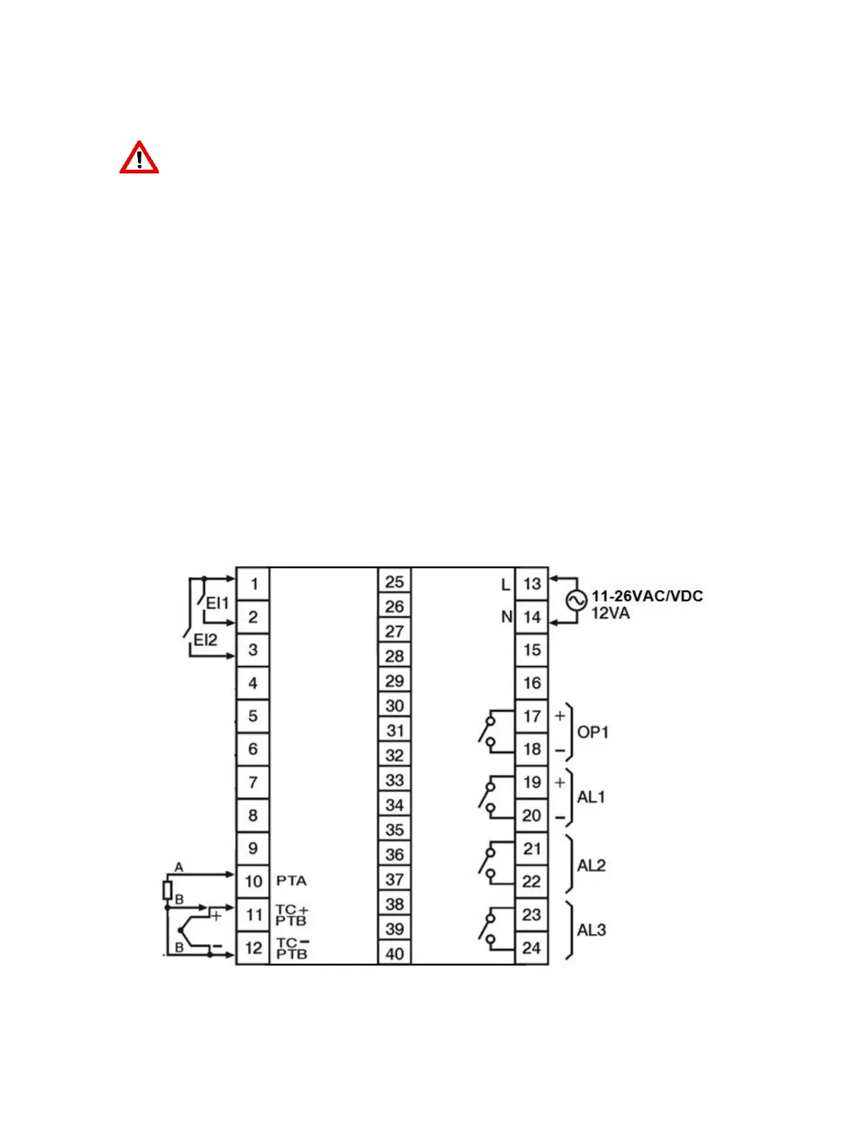
Rear Terminal Layout
 Loading...