Do you have a question about the Future Design LIMIT L91 and is the answer not in the manual?
Provides a general overview of the L91 limit controller's features and capabilities.
Details the product's ordering code structure and available options for configuration.
Explains the function and location of the programming port for setup and calibration.
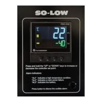
Describes the function of each key and the indicators on the front panel display.
Outlines the structure of the setup menu and available parameters.
Explains how the unit performs high, low, and high/low limit control operations.
Provides detailed descriptions of various parameters and their settings.
Guides users through unpacking the unit and preparing for panel mounting.
Lists essential safety and best practice precautions for wiring the unit.
Details the procedures for connecting the power supply to the unit.
Offers advice on optimal placement and selection of sensors for accurate readings.
Details the wiring connections for Thermocouple sensors.
Details the wiring connections for RTD sensors.
Details the wiring connections for linear voltage and current inputs.
Describes the wiring configuration for event input signals.
Explains the wiring methods for Output 1 functions.
Explains the wiring methods for Output 2 functions.
Covers wiring for RS-485 communication and analog retransmission.
Guides on selecting and configuring the process input type and units.
Explains limit control modes and setting the range for setpoints.
Details PV shift for value correction and digital filter for signal smoothing.
Describes configuration of process alarms, including modes and failure transfer.
Covers PC communication setup via RS-485, including address and baud rate.
Explains how to set the display format and configure DC power supply output.
Details configuration for remote reset and remote lock functionalities.
Describes the limit annunciator function and accessing reference data.
Illustrates an application example for over-temperature protection with remote reset.
Procedure for calibrating the zero point of the A to D converter.
Procedure for calibrating the gain of the A to D converter.
Procedure for calibrating the cold junction gain.
Outlines the product warranty terms and conditions provided by Future Design Controls.
States the limitations of the warranty and user responsibilities for product selection.
Provides instructions for obtaining authorization before returning a product.
| Brand | Future Design |
|---|---|
| Model | LIMIT L91 |
| Category | Controller |
| Language | English |