1
2
3
4
5
6
7
8
9
10
+
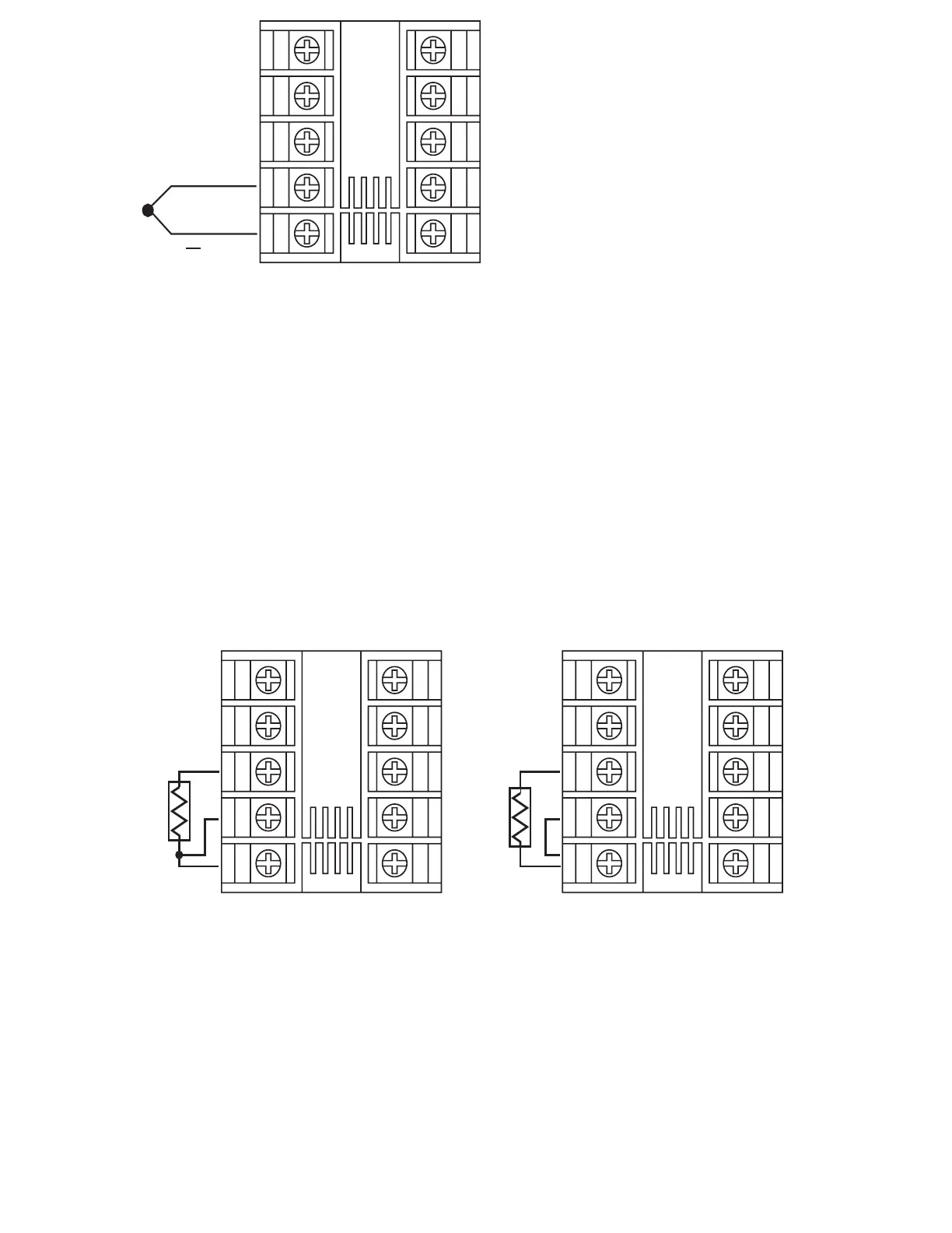
Figure 2.5
Thermocouple Input Wiring
Figure 2.5
Thermocouple
Input Wiring
RTD connection are shown in Figure 2-6, with the compensating lead
connected to terminal 4. For two-wire RTD inputs, terminals 4 and 5
should be linked. The three-wire RTD offers the capability of lead
resistance compensation provided that the three leads are of same
gauge and equal length.
2-7 RTD Input Wiring2-7 RTD Input Wiring
Two-wire RTD should be avoided, if possible, for the purpose of accuracy.
A 0.4 ohm lead resistance of a two-wire RTD will produce 1 degree C
temperature error.
1
2
3
4
5
6
7
8
9
10
RTD
1
2
3
4
5
6
7
8
9
10
RTD
Three-wire RTDThree-wire RTD Two-wire RTDTwo-wire RTD
Figure 2-6
RTD Input Wiring
Figure 2-6
RTD
Input Wiring
27
UM L91-Rev 8