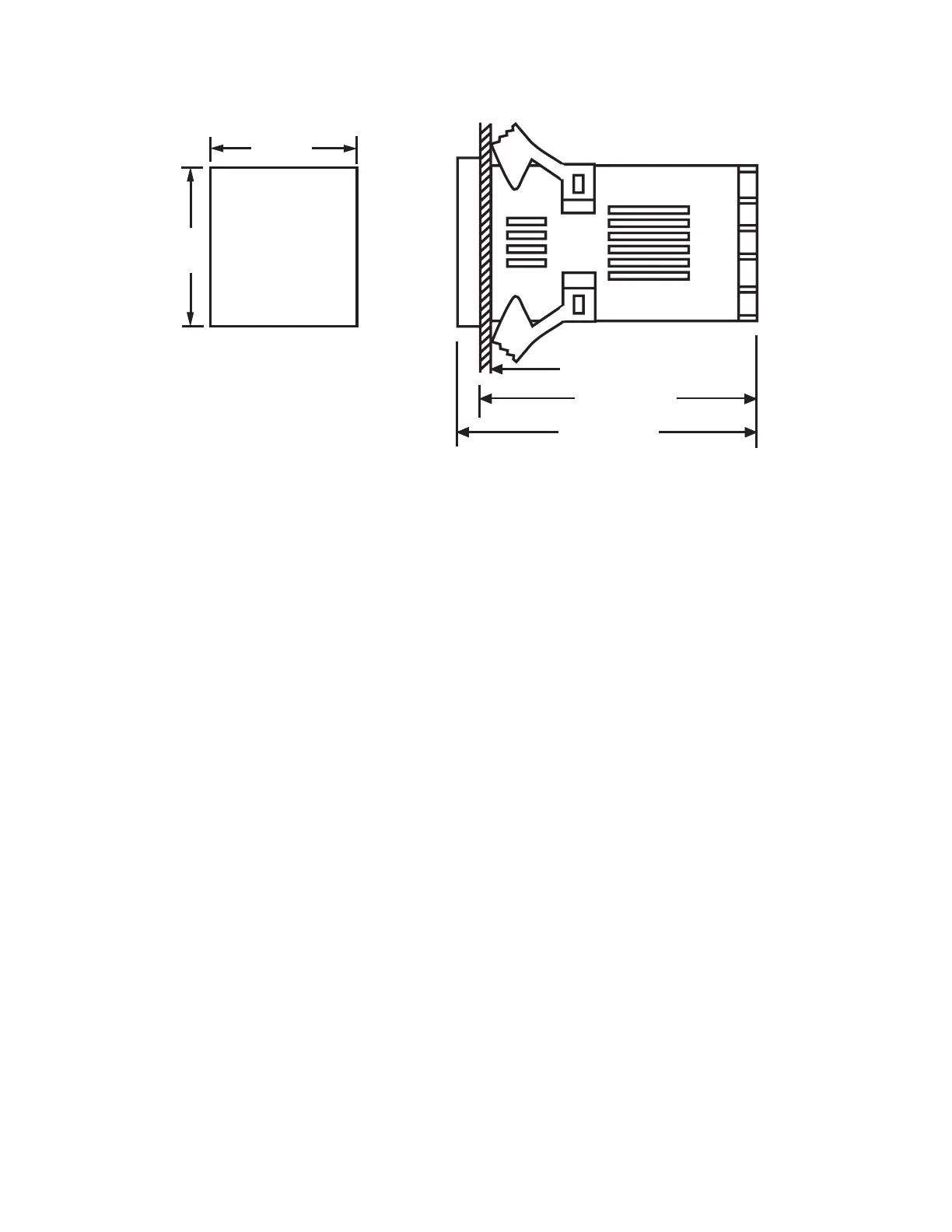
Install both mounting clamps and insert the housing into panel
cutout.
45
+0.5
_
0
45
+0.5
_
0
Panel cutout
Panel
86 mm
94 mm
Figure 2-1 Mounting DiagramFigure 2-1 Mounting Diagram
Before wiring, verify the label for correct model number and
options. Switch off the power when checking.
Care must be taken to ensure that maximum voltage rating
specified on the label are not exceeded.
It is recommended that power of these units to be protected by
fuses or circuit breakers rated at the minimum value possible.
All units should be installed inside a suitably grounded metal
enclosure to prevent live parts being accessible from human
hands and metal tools.
All wiring must conform to appropriate standards of good
practice and local codes and regulations. Wiring must be
suitable for maximum voltage, current, and temperature rating
of the system.
Take care not to over-tighten the terminal screws.
2 - 3 Wiring Precautions2 - 3 Wiring Precautions
*
*
*
*
*
*
23
UM L91-Rev 8