Unused control terminals should not be used as jumper points as
they may be internally connected, causing damage to the unit.
Verify that the ratings of the output devices and the inputs as
specified in Chapter 6 are not exceeded.
Electric power in industrial environments contains a certain
amount of noise in the form of transient voltage and spikes. This
electrical noise can enter and adversely affect the operation of
microprocessor-based controls. For this
reason we strongly recommend the use of shielded
thermocouple extension wire which connects the sensor to the
unit. This wire is a twisted-pair construction with foil wrap and drain
wire. The drain wire is to be attached to earth ground at the
sensor end only.
*
*
*
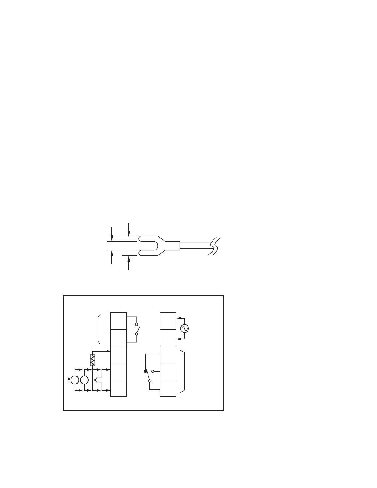
Figure 2-2 Lead TerminationFigure 2-2 Lead Termination
Figure 2-3 Rear Terminal
Connection Diagram
Figure 2-3 Rear Terminal
Connection
Diagram
1
2
3
4
5
6
7
8
9
10
_
_
+
+
_
_
+
+
I
B
B
A
RTD
V
TX2TX2
OUT2
RS-485
Retransmit
Event Input
OUT2
RS-485
Retransmit
Event
Input
TX1TX1
90-264VAC
47-63 Hz
10VA
90-264VAC
47-63
Hz
10VA
OUT1OUT1
2A
240 VAC
2A
240
VAC
2A
240 VAC
2A
240
VAC
PTAPTA
LL
NN
NCNC
NONO
CC
7.0mm max.
3.2mm min.
24
UM L91-Rev 8