Step 4: Calibrate of .
Setup the equipment same as step 3.
gain cold junctiongain cold junction
46
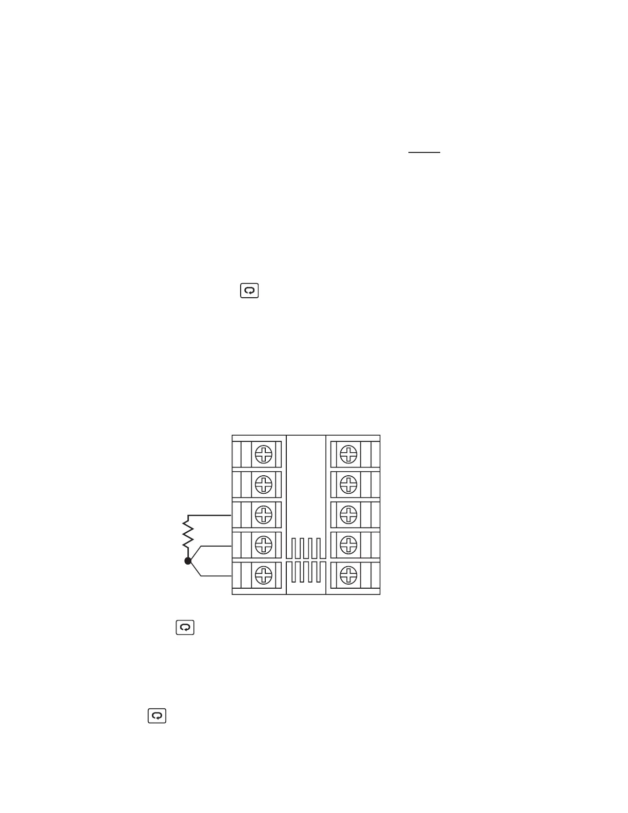
Step 5: Calibrate .
Send a 100 ohms signal to terminal 3, 4 and 5 according to
RTD reference voltage
Figure 5-3
.
RTD reference voltage
Figure
5-3
1
2
3
4
5
6
7
8
9
10
100 ohms
Figure 5-3
RTD Calibration
Figure 5-3
RTD
Calibration
Press for at least 4 seconds. The display will blink a
moment. If the display didn't blink, then the calibration failed.
Step 6: Calibrate .RTD serial resistanceRTD serial resistance
Change the ohm's value of the calibrator to 300 ohms. Press
for at least 4 seconds. The display will blink a moment.
If the display didn't blink, then the calibration failed.
UM L91-Rev 8
The L91 being calibrated for Cold Junction Compensation MUST
be programmed for K t/c input, Celsius display to performing
the CJG calibration.
prior
NOTE: The unit under calibration must powered at an
ambient temperature of 50C +/-3. Allow at least 20 minutes
for warming up.
NOTE: The unit under calibration must powered at an
ambient
temperature of 50C +/-3. Allow at least 20 minutes
for
warming up.
Set the calibrator to be configured as K type thermocouple
output. Calibrator must have an internal compensation.
Send a 0.00 C signal to the unit under calibration.
With CJG on the display adjust the value to 0.00 reading.
Once adjusted, Press for at least 4 seconds. The display will
blink a moment. If the display didn't blink, then the calibration
failed.