9 of 13
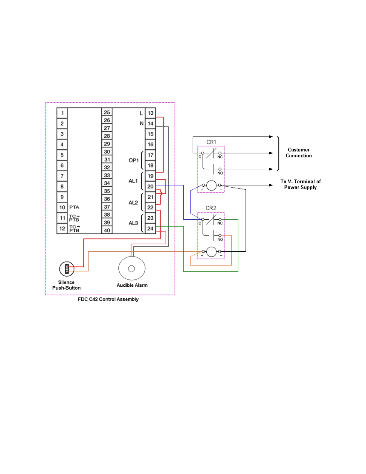
2.3.3 Alarm Relay Output /Audible Alarm
Connection to the alarm relays and audible alarm require external control relays that are not part of the
control assembly. One relay is utilized to provide remote contacts for customer connection for remote alarm
indication (shown as CR1 in the following diagram) and is optional. The other relay is utilized for the audible
alarm silence (shown as CR2 in the following diagram) which is required.
Note that alarm 3 (low battery) is utilized for indication only. When an alarm relay is energized, the
corresponding alarm indicator, AL1 for alarm 1 (temperature), AL2 for alarm 2 (power failure) or AL3 for
alarm 3 (low battery), will be illuminated on the upper left of the C42 LCD display. When either a high/low
temperature or power failure alarm activates, the audible alarm will sound as power from the alarm contact
will pass through the normally closed contact of relay CR2. When the silence button is pressed, the coil of
relay CR2 will be energized. Since the normally open contact of CR2 will then close, power will pass
through the relay contact and will in turn hold the relay coil energized even after the push-button is released.
This will hold the normally closed contact of the relay open, removing power from the audible alarm so that
it will no longer sound. Once both alarm conditions are no longer present, both alarm 1 and alarm 2 outputs
of the C42 will be de-energized. This will in turn remove power from the coil of relay CR2 causing it to de-
energize. This will then ensure that upon the next activation of either the temperature or power failure alarm
output, power will again pass to the audible alarm causing it to sound until the alarm condition clears or the
operator presses the silence button.
 Loading...