2.3.2 Sensor Installation Guidelines
Proper sensor installation can eliminate many problems in a control system. The sensor should be placed
so that it can detect any temperature change with minimal thermal lag. Some experimentation with sensor
location is often required to find the optimum position.
Proper sensor type is also very important to obtain precise measurements. The sensor must have the
correct temperature range to meet the process requirements. In special process, the sensor may need to
meet different requirements such as leak-proof, anti-vibration, antiseptic, etc.
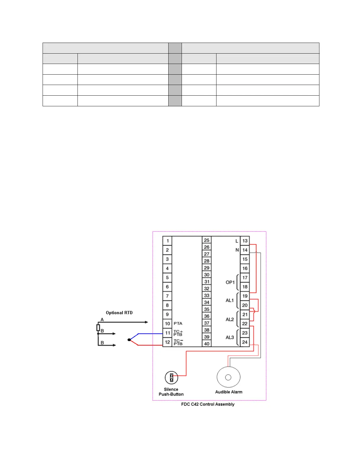
The FDC c42 control has been pre-configured for use with a “T” type thermocouple. The control is capable
of utilizing other thermocouple types and even RTD temperature sensors if required by simply reconfiguring
the input type selection. In the event of a sensor break, the upper LCD display will flash “SBER” and the
control relay output will de-energize.