Pre Installation set up and
testing (continued)
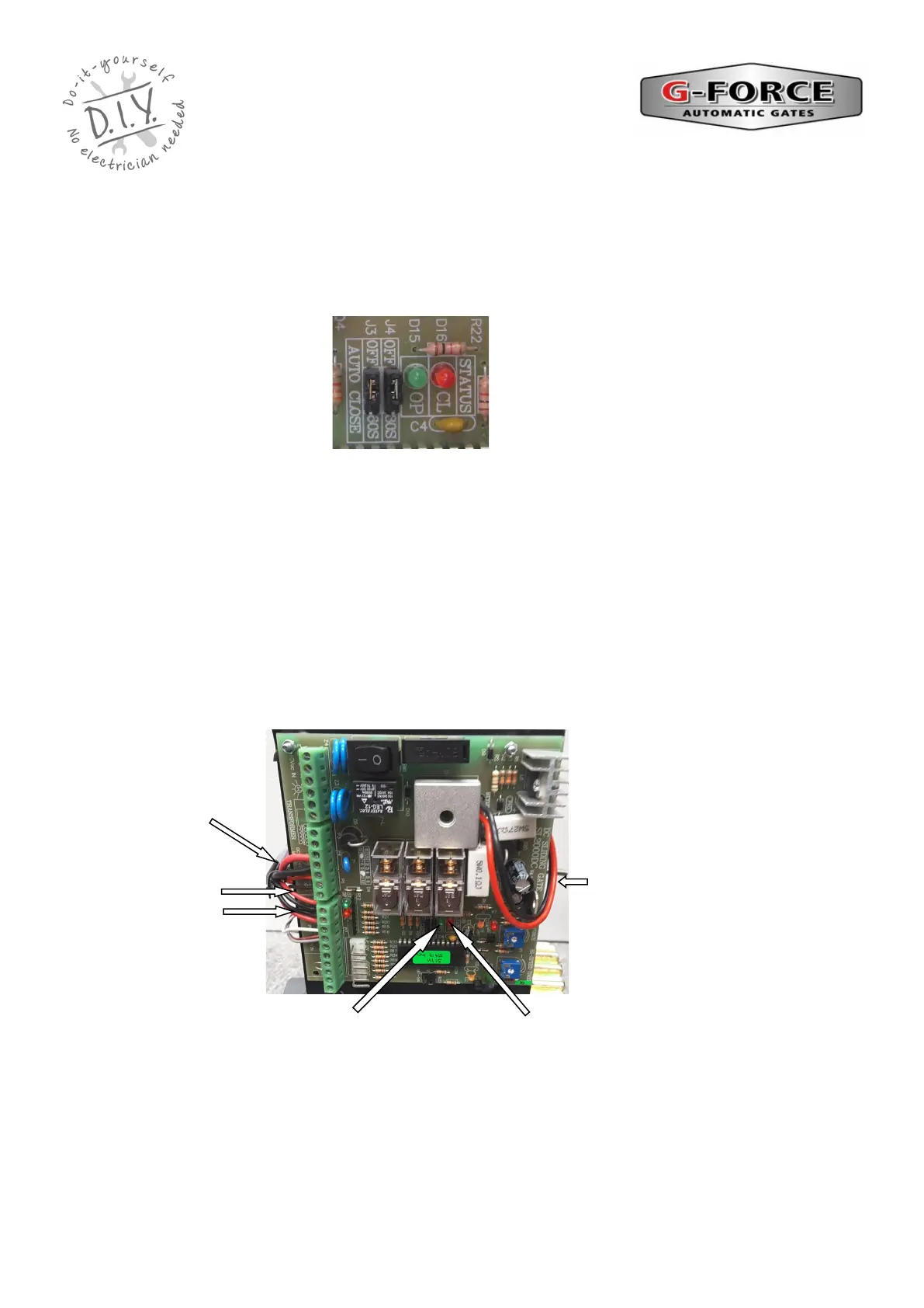
Setting Motor Direction
Refer to the “SL 2000 Circuit Board” data sheet included with this manual and locate the
direction LED’s on the circuit board. The GREEN LED (D15) indicates opening direction and the
RED LED (D16) indicates closing direction.
Activate the gate motor using the handset remote and check the rotation of the drive gear is
turning in the correct direction for opening the gate and the GREEN LED light is on OR the
correct direction for closing the gate and the RED LED light is on.
If the motor is going in the wrong direction, disconnect all power. Refer to the “SL 2000 Circuit
Board” data sheet included with this manual and locate the ‘DC 12/24V Motor’ terminals. on the
circuit board. Swap the red and black motor wires connected to ‘Motor terminals on the circuit
board. The red wire should be connected to the terminal that had the black wire connected to it
and the black wire should be connected to the terminal that had the red wire connected to it. This
will reverse the direction of the motor. Now locate the two RED limit switch wires and swap their
terminal positions around.
Activate the gate motor again using the handset remote and check the rotation of the drive gear
is turning in the correct direction for opening the gate and the GREEN LED light is on OR closing
the gate and the RED LED light is on.
RED Limit
Switch wires
Closing Direction
Red LED is on
Opening Direction
Green LED is on
Baery wires
DC 12/24V Motor
terminals.
RED and Black
wires.