EasyManua.ls Logo

G-U BKS B-1893 Series User Manual

G-U BKS B-1893 Series
140 pages
Go to English
To Next Page IconTo Next Page
Page #1 background imageLoading...
Page #1 background image
C
 | . | ES | Designed in Germany
TÜRTECHNIK | DOOR TECHNOLOGY
B-1893x | B-1993x
EN
14846
C!
EN
FR
ES
DE
Motortreibriegelschloss für Rohrrahmensysteme
Installationsanleitung .................................................................... SEITE | 2
Motor-driven shoot-bolt lock for narrow stile systems
Installation instructions ................................................................PAGE | 34
Contre-serrure motorisée pour profilés tubulaires
Instructions de montage ................................................................PAGE | 66
Cerradura con pestillo motorizada para sistemas de
marcos tubulares
Manual de instalación ............................................................... PÁGINA | 98

Table of Contents

Question and Answer IconNeed help?

Do you have a question about the G-U BKS B-1893 Series and is the answer not in the manual?

G-U BKS B-1893 Series Specifications

General IconGeneral
BrandG-U
ModelBKS B-1893 Series
CategoryLocks
LanguageEnglish

Summary

Safety Instructions and Definitions

General Information

Provides general information about the product and its installation.

Warning Symbols

Explains the meaning of warning symbols used in the manual.

Installation Notes

Details important notes and precautions for the installation process.

Description

Technical Data

Lists the technical specifications and data of the motor-driven shoot-bolt lock.

Scope of Delivery

Details the items included in the product package.

Accessories

Lists and describes optional accessories available for the system.

Connections

Explains the electrical connections and wiring for the lock system.

Installation

Preparatory Work

Outlines the necessary preparatory steps before commencing installation.

Installation Process

Provides detailed instructions for the physical installation of the lock.

Functions and Application

Manual Unlocking

Describes how to manually unlock the door lock.

Motor-driven Release

Explains the different modes of motor-driven door release.

Motor-driven Release of Active Leaf

Details the process of releasing only the active door leaf.

Motor-driven Release of Active and Passive Leaf

Explains releasing both the active and passive door leaves.

Voltage Loss During Motor-driven Operation

Describes the lock's behavior and requirements during power supply failures.

Motor-driven Daytime Release

Explains how to enable a permanent release function for daytime use.

Relay Outputs

Details the function and connection of the lock's relay outputs.

Signalling

Blink Codes

Explains the LED blink codes used for status indication and error reporting.

Acoustic Warning Signals

Describes the different acoustic signals emitted by the controller.

Programming Mode

Putting Controller into Programming Mode

Step-by-step guide to entering the controller's programming mode.

Exiting Programming Mode

Instructions on how to properly exit programming mode and save settings.

Acknowledging Blink Codes

How to acknowledge and clear error blink codes.

Changing Hold-open Time

Procedure for adjusting the hold-open time duration.

Performing a Test Run

Instructions for executing a test run to verify functionality.

Troubleshooting

Maintenance

Disposal

Appendix

B-1893x/B-1993x + B 1895

Technical drawings and specifications for B-1893x/B-1993x with B 1895.

Dimensioned Drawing

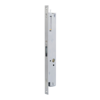
Detailed dimensioned drawings of the lock mechanism.

Profile Cutout

Illustrates the required profile cutout for installation.

Related product manuals