EasyManua.ls Logo

Gainsborough TRILOCK OMNI BB 8955 Series User Manual

Default Icon
4 pages
To Next Page IconTo Next Page
Page #1 background imageLoading...
Page #1 background image
Step 1.
• Fold template where indicated.
• Position template on door edge at
desired lock / latch height.
• Firmly hold template and mark latch
height and 2 off 60mm holes centres.
• Measure door thickness and mark
centre on 'latch height' marking.
• Drill 22mm (7/8") latch hole.
Note: it is important to drill this
hole squarely.
• Drill pilot holes [suggested size
3mm (1/8")]. Then enlarge holes to
60mm, drilling from both sides of the
door.
In particular, ensure the 60mm dia.
holes through door face are drilled
only to this size, otherwise correct
functioning may be impeded –
refer template.
Step 3.
• Mark and chisel latch faceplate to a recess of 2.5mm.
Use latch carrier as a template.
• Insert lock body into 60mm (2 3/8") slot.
• Insert latch carrier through 22mm
(7/8") hole into lock body assembly
and tighten with 2 screws.
Ensure T-shaped hole at rear
of latch carrier is upright!
Step 4a
Trilock Latch Bolt re-handing.
• Check that tapered side of the
Latch bolt faces towards the door jamb.
• It may be necessary to unclip
the rear arm & rotate bolt 180
• This is achieved by following steps:
Step 4.
• Insert the latch through the slot in the carrier until it can go no further.
• Insert the key and turn to retract the latch bolt.
Pre-drill wood screw holes with suitable drill size.
• Install plastic faceplate shim and faceplate, then screw into position.
Step 2.
• Mark vertical lines between
two holes as per illustration.
• Cut along marked lines
Please note: Ensure the template
position and orientation is as shown,
incorrect installation voids warranty.
template
Mark vertical lines between holes
as shown. Cut along vertical lines
NOTE: carefully follow these instructions when installing.
do not overtighten screws.
use of power driver is not recommended.
fully remove the Trilock prior to painting the door
to avoid harming the product's finish.
PAIT 147
NOV ‘12
Patent Pending
B
T Shape hole
Rear view
of latch
Latch
carrier
1. Remove Latch bolt assembly from carrier
4. Rotate Bolt 180˚ 5. Re-attach arm to latch bolt
6. Rotate arm up wards &
fit back into carrier
2. Rotate arm down wards
3. Unclip arm from latch bolt
Lock
body
Arm
Rotate Bolt 180˚
Installation Instructions for 8955 BB Series Omni Trilock
Twin Pull Handle Version - Suits 35mm to 45mm door thickness
Question and Answer IconNeed help?

Do you have a question about the Gainsborough TRILOCK OMNI BB 8955 Series and is the answer not in the manual?

Gainsborough TRILOCK OMNI BB 8955 Series Specifications

General IconGeneral
BrandGainsborough
ModelTRILOCK OMNI BB 8955 Series
CategoryDoor locks
LanguageEnglish

Summary

Omni Trilock Installation Guide

Step 1: Door Preparation and Drilling

Use template for door edge marking, drill latch hole and pilot holes for bolt.

Step 2: Door Edge Marking and Cutting

Mark vertical lines on door edge and cut along these lines.

Step 3: Latch Fitting and Chisel Recess

Chisel a 2.5mm recess for the faceplate and fit the latch body.

Step 4: Latch Bolt Installation

Insert latch bolt into carrier, secure with screws, and fit the faceplate.

Step 4a: Latch Bolt Re-handing

Adjust latch bolt orientation by re-attaching its arm for correct door jamb alignment.

Step 5: Marking Additional Holes

Use template to mark remaining holes on door sides for mounting hardware.

Step 6: External Lever Re-handing

Adjust external lever operation by relocating the stop screw if needed.

Step 7: Installing Faceplate Posts

Insert two posts into the external Trilock faceplate before mounting.

Step 8: Mounting Inside Faceplate

Align the inside faceplate gear with the lock body gear for correct engagement.

Step 9: Installing Snib Rotor and Furniture

Fit snib rotor, align furniture plates, and secure with mounting screws.

Step 10: Internal Turnbutton Installation

Install the internal turnbutton for single cylinder applications.

Step 11: Fitting Door Seals and Strike Plate

Fit all door seals, mark and install the strike plate on the door frame.

Step 13: Fixing Double Pull Handle

Mount pull handles by securing M8 bolt through door and attaching handles.

General Installation Notes

Important Installation Precautions

Follow instructions carefully, avoid overtightening, and remove Trilock for painting.

Door Adjustment for Strike Plate

Adjust bolt latching and strike plate for proper door closure and rattle-free operation.

Exploded Diagram

Component Overview

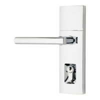
Visual breakdown of all parts included in the Omni Trilock set.

Related product manuals