Do you have a question about the Galaxy DX95T2 and is the answer not in the manual?
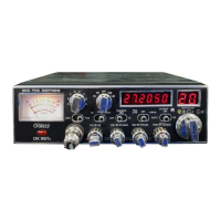
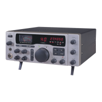
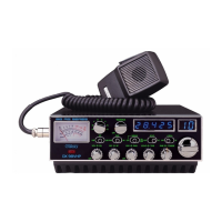
Identifies the radio model DX95T2 and its operational frequency range from 28.315 to 28.755 MHz.
Specifies supported emission modes (FM/AM/USB/LSB) and the phase-lock-loop frequency control.
Details frequency stability, temperature range, and impedance requirements for optimal performance.
States the antenna connector type (SO-239) and required input voltage (13.8V DC).
Specifies RF power output for AM/FM (2W-50W) and USB/LSB (150W PEP).
Details receiver sensitivity levels for different modes (AM, USB/LSB, FM) in microvolts.
Defines selectivity (-55 dB) and image rejection (-50 dB) for filtering unwanted signals.
Specifies the audio power output capability of the radio at 10% distortion.
Guidance on choosing a convenient and mechanically secure location for radio installation.
Instructions for connecting the antenna and wiring the radio to the vehicle's power system.
Emphasizes the importance of good grounding and robust DC connections for optimal performance.
Steps for mounting the microphone bracket in an accessible location.
Explains use of NB/ANL circuits and engine off operation to reduce background noise.
Discusses antenna types, matching for range, and adjustment for optimal performance.
Details for connecting an external speaker, including impedance and power handling.
Instructions for using the Public Address (PA) function with an external speaker.
Describes the modulation indicator lamp and its behavior across different signal strengths.
Explains the switch that controls the meter's function for SWR, modulation, or power output.
Identifies the port used for connecting the external microphone.
Details the ON/OFF Volume knob for controlling power and receiver audio levels.
Describes how to use the squelch knob to eliminate background receiver noise.
Explains adjusting microphone gain and the push-button function for Talkback.
Details the RF Gain knob for adjusting the level of incoming signals.
Explains the Dim control for brightness and a push-button to turn the frequency display off.
Describes the control for adjusting the radio's RF power output.
Details the Coarse/Fine tuning and a push-button to activate Noise Blanker/ANL.
Explains the RX/TX/OFF/RX switch for controlling clarifier functions during operation.
Identifies the control used for selecting the desired transmit and receive channel.
Indicates the status of the Talkback function with a green LED.
Details the two-year limited parts and labor warranty for factory defects.
Outlines steps for obtaining warranty service, including calling for a RAN.
Provides guidance on shipping the radio for repair and return shipping responsibilities.
| Frequency Range | 26.965 MHz - 27.405 MHz |
|---|---|
| Channels | 40 |
| Image Rejection | 60 dB |
| Power Supply | 13.8 VDC |
| Modes | AM/SSB |
| RF Output Power | 4W AM/FM, 12W SSB |
| Output Power | 4W AM/FM, 12W SSB |
| Receiver Sensitivity | 0.25μV (SSB), 0.5μV (AM) |
| Antenna Impedance | 50 Ohms |
| Microphone | Dynamic |