A
Allison CoxAug 16, 2025
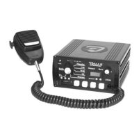
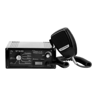
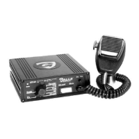
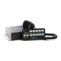
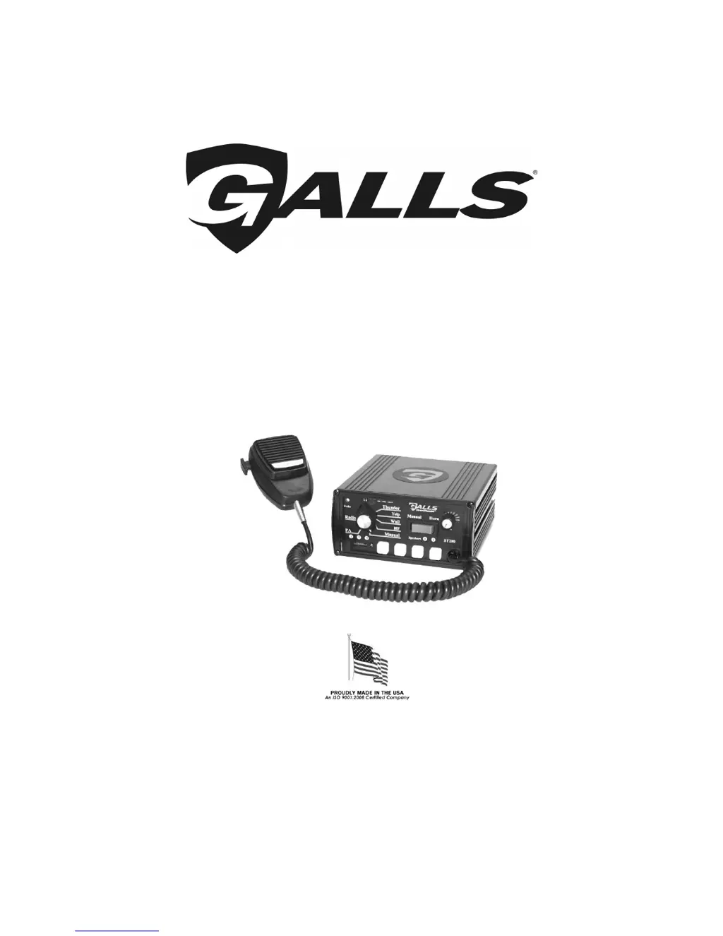
What to do if my Galls Amplifier has no power?
- VveronicajohnsonAug 16, 2025
If your Galls Amplifier has no power, make sure the On/Off PA Vol. Knob is not in the OFF position. Also, check if the yellow wire is connected to switched +12VDC, examine the connector, and verify that the power is not hooked up backwards. Ensure that it is not a positive ground vehicle. Check if an external fuse or circuit breaker is used and confirm that the negative leads are connected to a good ground.