-7-
(Electrical Connections CONT’D)
Positive
Switching AUX
Horn Jumper
Selected
Negative
Switching AUX
Horn Jumper
Selected
Backlighting Switch (Connect to
Dash Lights, Parking Lights, Etc.)
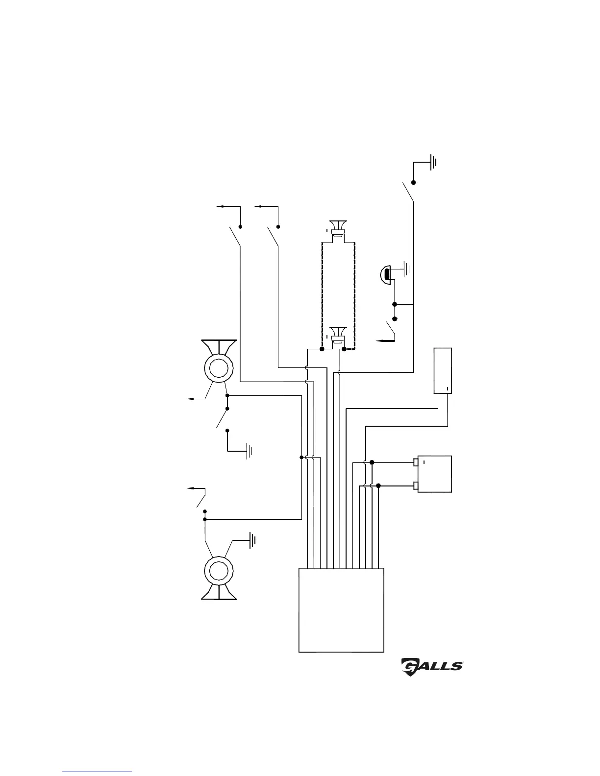
Siren Wiring Diagram
+12 VDC +12 VDC
Horn
Switch/Relay
VEHICLE
HORN
Horn
Switch/Relay
OR
ON/OFF Power Switch for Siren
(Possibly Connected to Ignition)
+12 VDC
VEHICLE
HORN
+12 VDC
+12 VDC
+
SIREN
AMPLIFIER
9 - Orange (#18 AWG)
11 - Yellow (#18 AWG)
12 - Brown (#14 AWG)
10 - Green (#18 AWG)
8 - Gray (#18 AWG)
6 - Blue (#18 AWG)
7 - Brown (#14 AWG)
2 - Black (#14 AWG)
4 - Red (#14 AWG)
5 - Black (#14 AWG)
3 - Blue (#18 AWG)
1 - Red (#14 AWG)
+
SPEAKER 2
11 OHMS
SPEAKER 1
11 OHMS
Negative Switching PK
Jumper Selected
Positive Switching PK
Jumper Selected
OR
Dome
Light
Door Switch
+
RADIO
+
Connect the Blue wires to
the terminals of speaker or
to the output jack of radio
BATTERY
Added Door
Switch