EasyManua.ls Logo

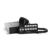
Galls ST300 - Light Relay Control Box Connections

Galls ST300
28 pages
Print Icon
To Next Page IconTo Next Page
To Previous Page IconTo Previous Page
Loading...
-14-
12 - Brown (#14 AWG)
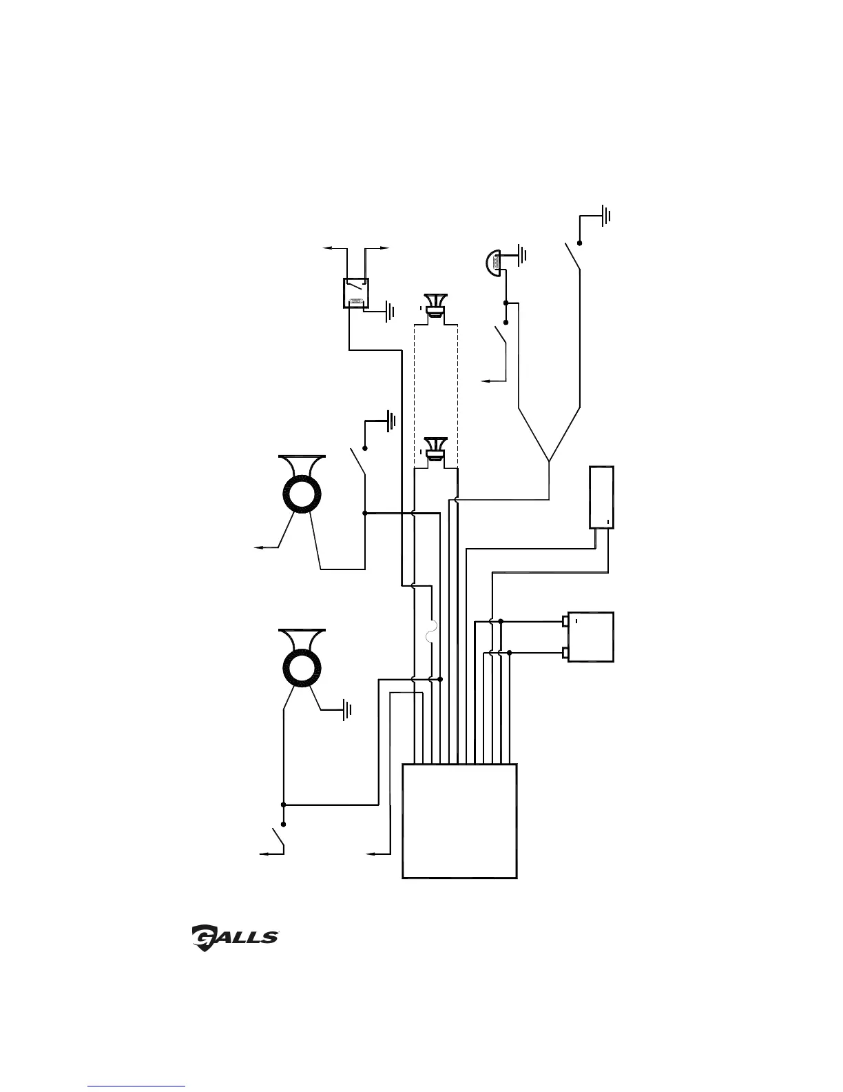
Siren Wiring Diagram
Positive
Switching
AUX
Positive Switching AUX
Horn Jumper Selected
+12 VDC
+12 VDC
Ignition controlled
power or other
switched power source
Horn
Switch/Relay
Negative Switching AUX
Horn Jumper Selected
+12 VDC
Horn
Switch/Relay
OR
VEHICLE
HORN
VEHICLE
HORN
Negative
Switching
AUX
+12 VDC
Optional Relay Activated
When PB5 is Turned On
To High Current Device
5 - Black (#14 AWG)
SIREN
AMPLIFIER
11 - Pink (#18 AWG)
10 - Orange (#18 AWG)
9 - Green (#18 AWG)
OR
8 - White (#18 AWG)
7 - Brown (#14 AWG)
6 - Blue (#18 AWG)
1 - Red (#14 AWG)
4 - Red (#14 AWG)
3 - Blue (#18 AWG)
2 - Black (#14 AWG)
Positive Switching PK
Jumper Selected
+12 VDC
2 Amp fuse
SPEAKER 1
11 OHMS
+
SPEAKER 2
11 OHMS
+
Door Switch
Dome
Light
Negative Switching PK
Jumper Selected
RADIO
+
Connect the Blue wires to
the terminals of speaker or
to the output jack of radio
+
BATTERY
OR
Added Door
Switch
(Electrical Connections CONT’D)