CAUTION
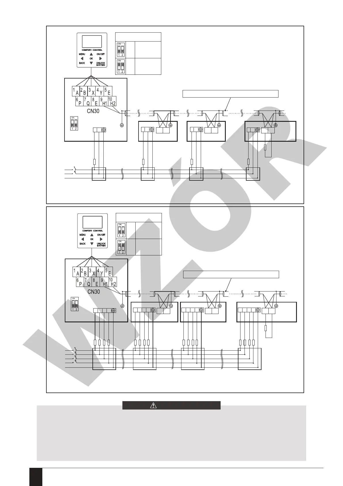
Indoors
Power supply
Please use the shielded wire, and the shield layer must be grounded.
On/Off switch
Fuse
Distribution box Distribution box Distribution box Distribution box
Fuse Fuse Fuse
L N
L N L N
L N
Master unit
Slave unit 1
H1 H2
Slave unit 2
H1 H2
Slave unit x
H1 H2
Build-out resistor
Only the last IDU
requires adding the
build-out resistor at
H1 and H2.
......
SW9
Power supply
Please use the shielded wire, and the shield layer must be grounded.
On/Off switch
Fuse
Distribution box Distribution box Distribution box Distribution box
The cascade system electrical control system connection diagram(3N~)
Master unit
Slave unit 1
H1 H2
Slave unit 2
H1 H2
Slave unit x
H1 H2
Build-out resistor
Only the last IDU
requires adding the
build-out resistor at
H1 and H2
......
SW9
L1 L2 L3 N
Fuse
L1 L2 L3 N
Fuse
L1 L2 L3 N
Fuse
L1 L2 L3 N
1、The cascade function of the system only supports 6 machines at most.
2、In order to ensure the success of automatic addressing, all machines must be connected to the same power
supply and powered on uniformly.
3、Only the Master unit can connect the controller, and you must put the SW9 to “on” of the master unit, the slave
unit cannot connect the controller .
4、Please use the shielded wire, and the shield layer must be grounded.
The cascade system electrical control system connection diagram(1N~)
ON
OFF
SW9
Slave unit
Master unit
ON
OFF
SW9
Slave unit
Master unit
Installation and operation manual - air-water heat pump Prima © All rights reserved - Galmet Sp. z o.o. Sp. K.130
 Loading...