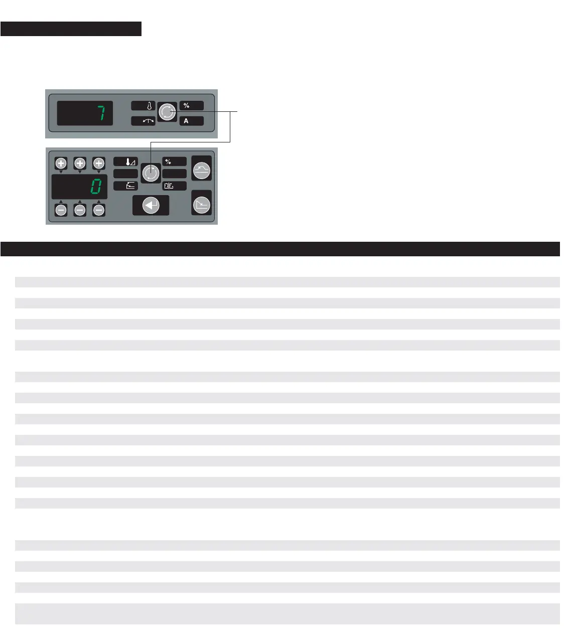
hold and release. Selection LED’s go dark when in Setup Mode.
Guide.
# Limit (Default) Explanation
(0) 0-4 (0) Restore Mold Set Up - Access Setup, 0-View Area, Select Mold Set Up 1-4 - Change Area, Enter
(1) 0-4 (0) Save Mold Set Up - Access Setup, 1-View Area, Save As 1-4 - Change Area, Enter
(2) +/- 100F or 50C (20F) Boost Set Point, Timed Automatic Temporary Set Point Change for the selected zones
(3) 999 Seconds (60 Sec) Boost Time Set Point - The amount of time the selected zone or zones will change temporarily
(4) 932F or 500C (932F) Automatic Set Point Limit - The Maximum Set Point the operator can enter in Automatic
(5) +/- 100F or 50C (20F) Temperature Deviation Alarm Set Point - Set Point activates temperature alarm at that # +/-
(6) 600F or 315C (220F) Standby Set Point - When Standby is Selected it will control to this number in Automatic
(7) -1 to 27 (0) Control Algorithm Adjustment, 0=Auto Select (1=Tip Tuning; 2=Man. Tuning). Manual Selections:
-1=Faster Control (Tips), 10=Tip; 11-17=Tip with increasing lag, 20=Manifold, 21-27=Manifold with increasing lag
(8) -1 to 2 (0) T/C Pinch Detection Time, 0 Normal = 100% Output, 20F in 5 Min. -1 Faster (Tips), 1-2 Slower (Manifolds)
(9) 0 or 1 (0) Slaved Power Up - Heat all zones to Set Point within 20F of one another, 0 - “Off ” 1 – “On”
(10) 0 or 1 (0) Degree F or C Selectable, 0 = Degree F, 1= Degree C
(11) 0 or 1 (0) Type J or K Thermocouple Input, 0 = Type J, 1 = Type K
(12) 0 or 1 (0) Host Computer Protocol, 0 = Gammaflux Protocol (Mold Doctor, etc.), 1 = Euromap 17 Protocol
(13) 0-99 (0) Network Port Device Number – The address of the controller on the Euromap 17 Network.
(14) 0-3 (0) Host Baud Rate – Communication Speed; 0=9600, 1=4800, 2=2400, 3=1200
(15) - - - Reserved for Future Use
(16) - - - Reserved for Future Use
(17) 000 - 999 (None) Security Code Level 1 – You Must be in Level 2 to Change, Refresh procedure available, call the factory
(18) 000 - 999 (None) Security Code Level 2 – You Must be in Level 2 to Change, Refresh procedure available, call the factory
(19) 0-999 (Custom) Zone Finder – Activate Press 999, Hundreds show T/C inputs 1-3 Tiers, Tens/Ones show # of Output Modules
(20) 0 (0) LED Test - Enter 0, Press Enter. Turns “On” all LED’s for Troubleshooting
(21) 0-6 (0) Error Status, Select Zone, View Error. 0=No Error, 1=No Communication, 2=Zone Not Allocated,
3=Output Controller Not Receiving Temperatures, 4=No Sync/Lost Phase,
5=Communication Error/Checksum, 6=Communication Error/Exceeded Limit
(22) - - - Output Controller Software Version Number (Display Only), Select Zone, Version Displayed
(23) - - - Output Controller Software Revision Number (Display Only), Select Zone, Revision Displayed
(24) - - - Temperature Module Software Version Number (Display Only), Select Zone, Version Displayed
(25) - - - Temperature Module Software Revision Number (Display Only), Select Zone, Revision Displayed
(26) - - - Operators Panel Software Version Number (Display Only), Select Zone, Version Displayed
(27) - - - Operators Panel Software Revision Number (Display Only), Select Zone, Revision Displayed
(28) 000 - 999 (Level 2) Security Level Indicated, 0=Lockout, 1=Operator, 2=Supervisor. 0 - Enter, Drops one Level.
Elevate One Security Level at a Time with your Customized Code. Then Press Enter.
 Loading...