Page 7
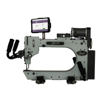
Gammill Vision™ - Right SideView
The right side of the Gammill Vision™ has the threading path and tension devices.
1. Thread Path – Threading the machine can seem complicated but it is actually easy because
the thread guides clearly mark the path. In this example, thread comes off the cone, going straight up
into the first guide called the thread lead-off. There are two more guides that take it into the intermittent tension
assembly, and it is wrapped around the silver cylinder (which is a thread break sensor wheel) and then to
another guide and to the rotary tension assembly. Two ‘L’ shaped guides help keep the thread in the check
spring. From there it goes to the take up lever, through more guides and finally through the eye of the needle.
Detailed threading instructions are given in the following pages.
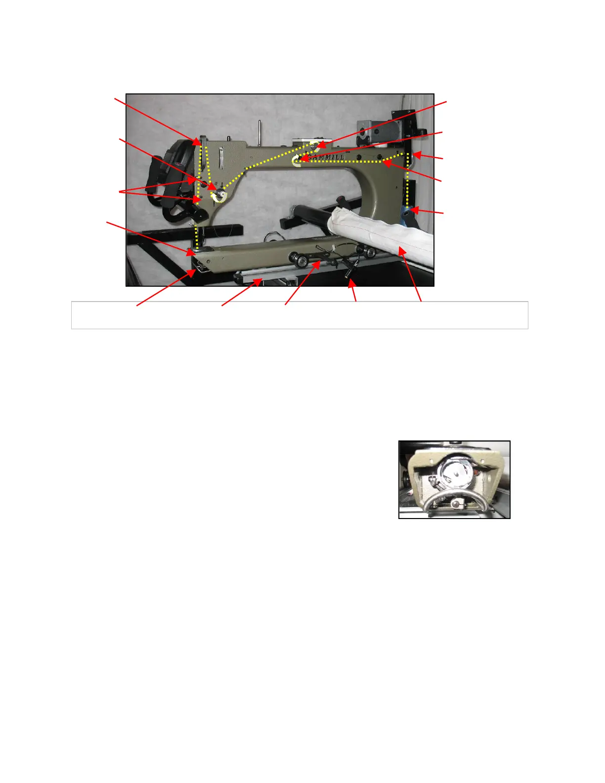
2. Bobbin Area – is the open area below the needle. The bobbin
and bobbin case are larger than most domestic sewing
machines so they hold more thread, and run out less often.
The sewing hook (also known as hook race or hook) spins around the
bobbin, catching the thread and making the stitch. Be sure nothing ever
obstructs this motion. This area will look familiar very soon since you will
clean the bobbin area with a small brush every time the bobbin is
changed. .
3. Crosstrack – Also known as the carriage, is a platform that holds the machine. It has two
tracks so the machine can roll front-to-back. It sits on two tracks on the table which allow it to roll left to right.
The crosstrack has the vertical channel lock attached as well as one of the encoders for the stitch-regulator.
4. “T” Bar is a bracket shaped like a ‘T’ that is screwed into the side of the machine. The bracket
can hold the stylus vertically when it is being used to align the machine with a mechanical template like the
WorkStation or the Design Center. The bracket can also hold the stylus horizontally for attaching the adjustable
laser clamp when it is being used to hold the laser light while stitching pantographs.
5. Laser Light – is being held in a special clamp that allows it to be turned so it points in
virtually any direction. When attached to the ‘T’ bracket, as shown here, the laser light is used to follow
pantographs which are stitched from the back of the machine. When using the laser light at the back, plug it
into the Power Enclosure on the left side at the back of the machine. It only fits in one place on the Power
Enclosure.
The laser light and clamp can also be moved to the front for use when working at the front of the
machine, as shown in the next paragraphs.
 Loading...