GANSHORN Medizin Electronic GmbH Service Manual Ref.No. 03 140 0 046
PowerCube-Ergo-CASE_ENG_rev.02, 23.11.2012 Chapter 2, system description , page 6 of 10
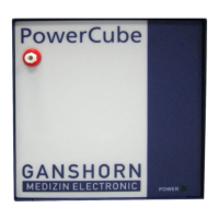
Tubing Bock Diagram
Pict.: Block diagram PowerCube-Ergo, tubing general
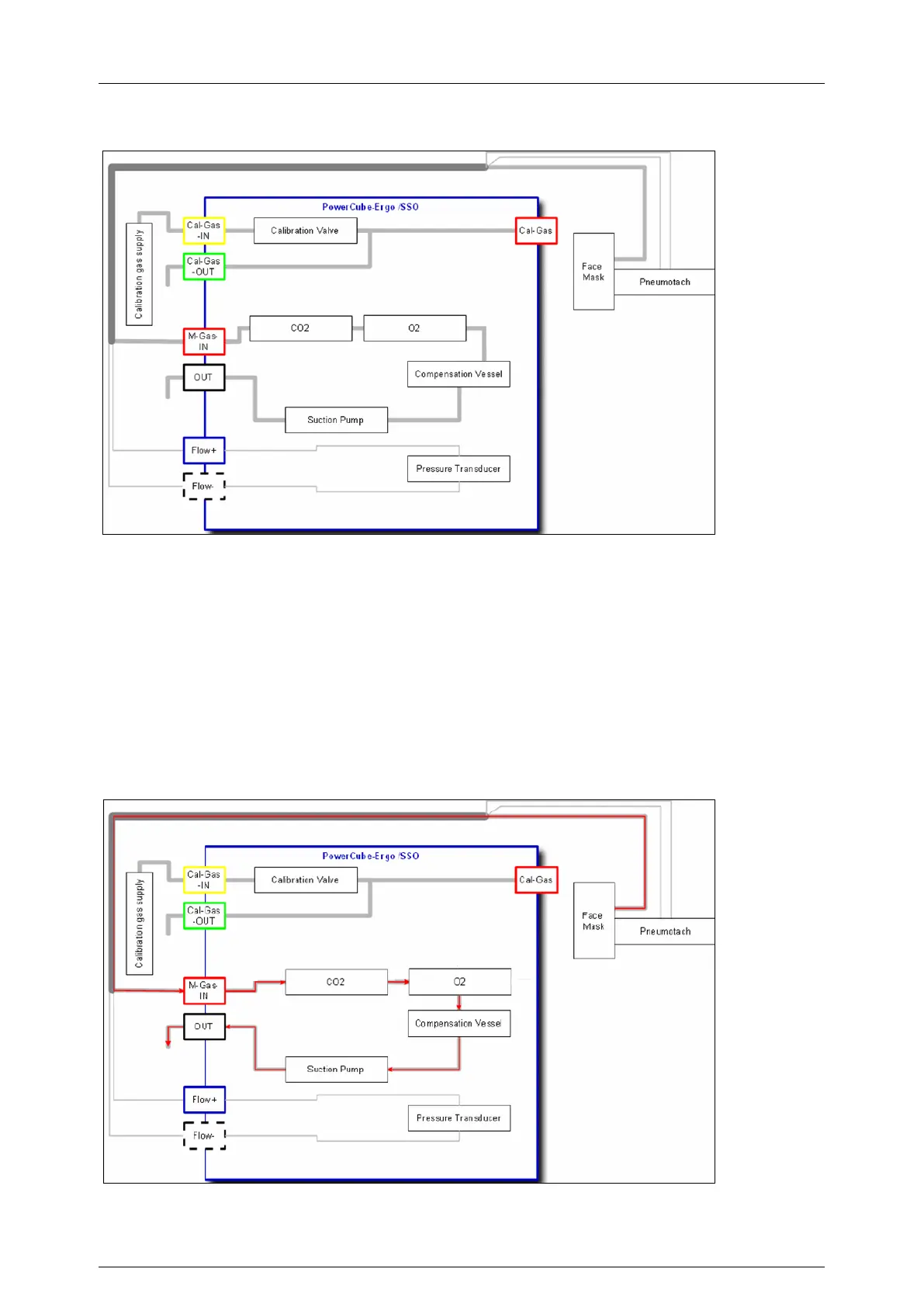
Gas flow to the analyzers during ergospiromety measurement
The suction pump assures the gas flow inside the tubing and the PowerCube.
It sucks the gas sample (measurement gas)
from the gas connectors of the face mask / mouth piece
through the gas drying tube / patient tube
through both gas analyzers (O2, CO2)
through the compensation vessel
The gas sample leaves the PowerCube through the suction pump and the sound absorber
Pict.: Block diagram PowerCube-Ergo, gas flow during an ergopirometry-measurement
(Red: gas sample, measurement gas)
 Loading...