GANSHORN Medizin Electronic GmbH Service Manual Ref.No. 03 140 0 046
PowerCube-Ergo-CASE_ENG_rev.02, 23.11.2012 Chapter 2, system description , page 7 of 10
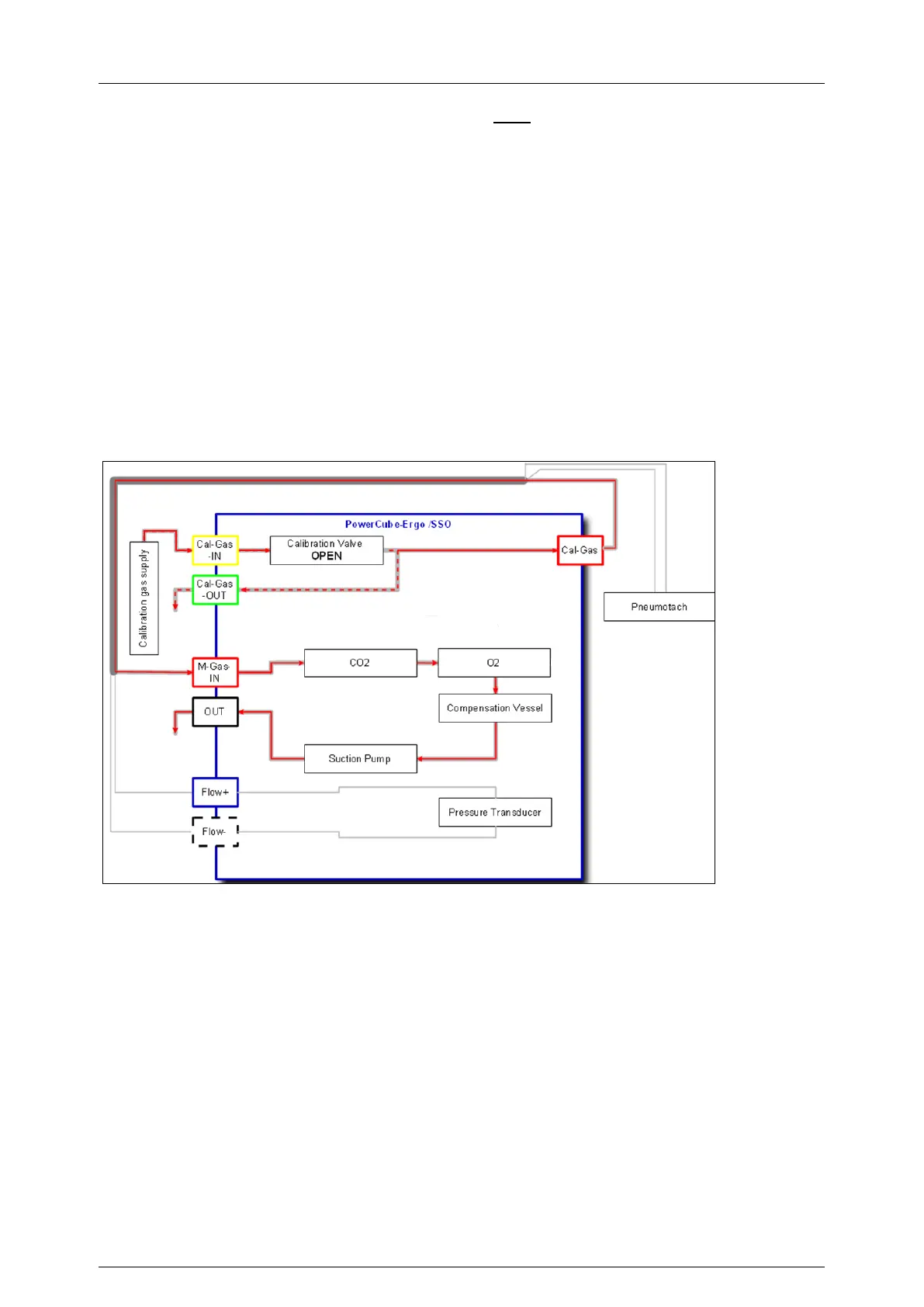
Gas flow to the analyzers during gas calibration with open calibration gas valve:
When the calibration valve is opened,
the pressure reducer provides calibration gas coming from the calibration gas bottle
through the calibration gas connection tube
through the Cal-gas-in-socket
to the calibration gas valve
into the T-piece
through the second end of the T-piece and the Cal-gas-out-socket into the room air
The suction pump sucks the gas sample (calibration gas)
from the third end of the T-piece
through the calibration gas socket on the front of the PowerCube
through the gas drying tube / patient tube
through both gas analyzers (O2, CO2)
through the compensation vessel
The gas sample leaves the PowerCube through the pump and the sound absorber
Pict.: Block diagram PowerCube-Ergo, gas flow during a ergo-calibration (gas calibration),
calibration valve open (Red: gas sample from calibration gas. Dashed line: calibration gas)
 Loading...