3
www.gantner.com
Valid as from September 27
th
2013 • Technical data subject to modifications without notice!
DB_GAT-NET-Lock7000--EN_20.indd • Art.Nr.: 573734
Mounting and Installation Instructions
TheGATNET.Lock7000ismountedwith3screws(1)ontheinsideofthe
locker. The bolt set with the door shackle is mounted on the inside of the
lockerdoor.Atnon-metallicdoorsonlyadrillingfortheLEDisrequired.At
metallic doors a cut-out must be made in the door, where the bolt set and
label carrier will be mounted.
Door status contact
The GAT NET.Lock 7000 has a contact which gets activated by the door
contact (5) at the bolt set as soon as the locker door is closed. This allows
to determine the open/close state of the door. To guarantee the correct
functionality of the GAT NET.Lock 7000 it is important that this contact is
clean and not damaged.
Mounting on Non-Metallic Doors
Installation measures for GAT NET.Lock 7000 and Bolt Set
During the mounting, please pay particular attention to the following points:
- Whenthedoorispressedshut,thegapbetweentheboltset(2)andthe
frontoftheGATNET.Lock7000mustnotbeexceed0.5mm.Ideallythe
bolt set should touch the front of the lock.
- Themiddleofthedoorshackle(4)mustbe1mmhigherthanthemiddle
of the door shackle opening in the GAT NET.Lock 7000. This ensures
thedoor’sabilitytocloseevenifthedoorpositionismodified3mm
downwardsor1mmupwards(tolerance±2mm).
Mounting procedure
Note: Before mounting all locks of the locker system a test installation of
at least one lock and final function check must be performed like
described below. Only if the tests are successful the rest of the
locks may be mounted in the same way.
1. Drillthethreeholes(3)fortheGATNET.Lock7000intothelocker
wall.
2. Plug-intheconnectioncable(seepage6).
Door width
The minimum allowed door width (measured from the door shackle to the
hinge) is 230 mm. If the door is narrower than this measure, the door
shackle would hit the locker when the door is being closed.
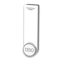
1.GATNET.Lock7000
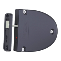
2.GATNET.LockBoltSet7100
3.Mounting screws for GAT NET.Lock 7000
4. Door shackle
5. Door contact
6.Mountingscrewsforboltset
7. LED (hole in locker door)
3. MounttheGATNET.Lock7000withthreescrews(3)onthe inside
locker wall.
Note: Use the right screws according to the type of locker material.
Attention:Themax. allowed tightening torque of thescrews
is 2 Nm.
4. Drillthethreeholes(6)formountingtheGATNET.LockBoltSet7100.
5. Drill a hole for the LED display in the locker door (7). The recommended
holediameteris10mm.
Note:AfrontlabelcanbeusedtocovertheLEDhole.Ifthecustomer
designs the label he must pay attention that a transparent field for the
LED light should be placed on the label.
6. Mounttheboltsetontothelockerdoorbyusingthreescrews.
Note: Use the right type and length of the screws according to the
type of locker material.
Attention:Themax. allowed tightening torque of thescrews
is 2 Nm.
7. Close the locker door to test, if the door can be closed easily and the
door shackle inserts into the opening in the GAT NET.Lock 7000.
50.0 mm
6.0 mm
94.0 mm
60.1 mm
1.0 mm
Middle of the opening
for the door shakle
Locker door
3
6
6
3
3
3
3
74.0 mm
17.0 mm
17.0 - 17.5 mm
2.4 mm
10.1 mm
14.6 mm
17.6 mm
25.1 mm
6.6 mm
1
2
4
8.0 mm
33.6 mm
82 mm
1
2
6
6
7
7
5
3
Locker door
Centre of rotation of hinge
min. 230 mm
Locker wall
Locker wall
 Loading...