12 711
21 20 16 15 14 1319 18 17
610 59 48 3
G
H
22
1
2
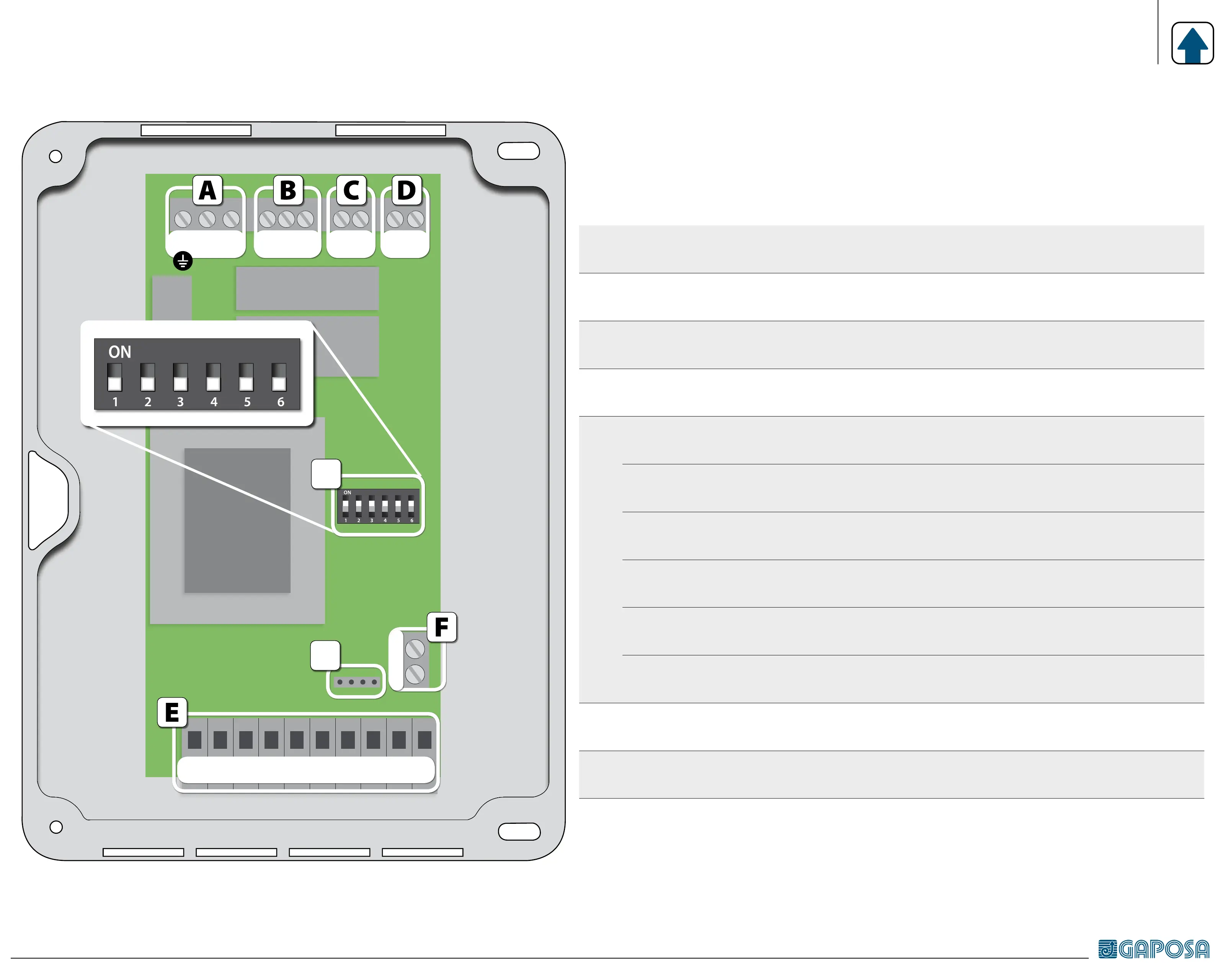
ELECTRICAL CONNECTION
A
20 - 21 - 22
Power supply 1-phase (230 v~) (ground = 22)
B
17 - 18 - 19
Motor (comune = 18)
C
16 - 15
Flashing light [230V~]
D
14 - 13
Courtesy lamp (contact normally open - no)
E
12 - 11
Power supply external accessories (24 V~)
10 - 9 [COM]
Safety photocells or bar (contact normally closed - nc)
8 - 9 [COM]
Safety stop (contact normally closed - nc)
7 - 5
Start / stop (contact normally open - no)
6 - 5
Close (contact normally open - no)
4 - 5
Open (contact normally open - no)
F
1 - 2
Antenna: connect the antenna to terminal 1
In case of cable with shielding, this has to be connected to terminal 2.
G
KB connector for integrated keyboard
H
DIP SWITCH for control unit setup