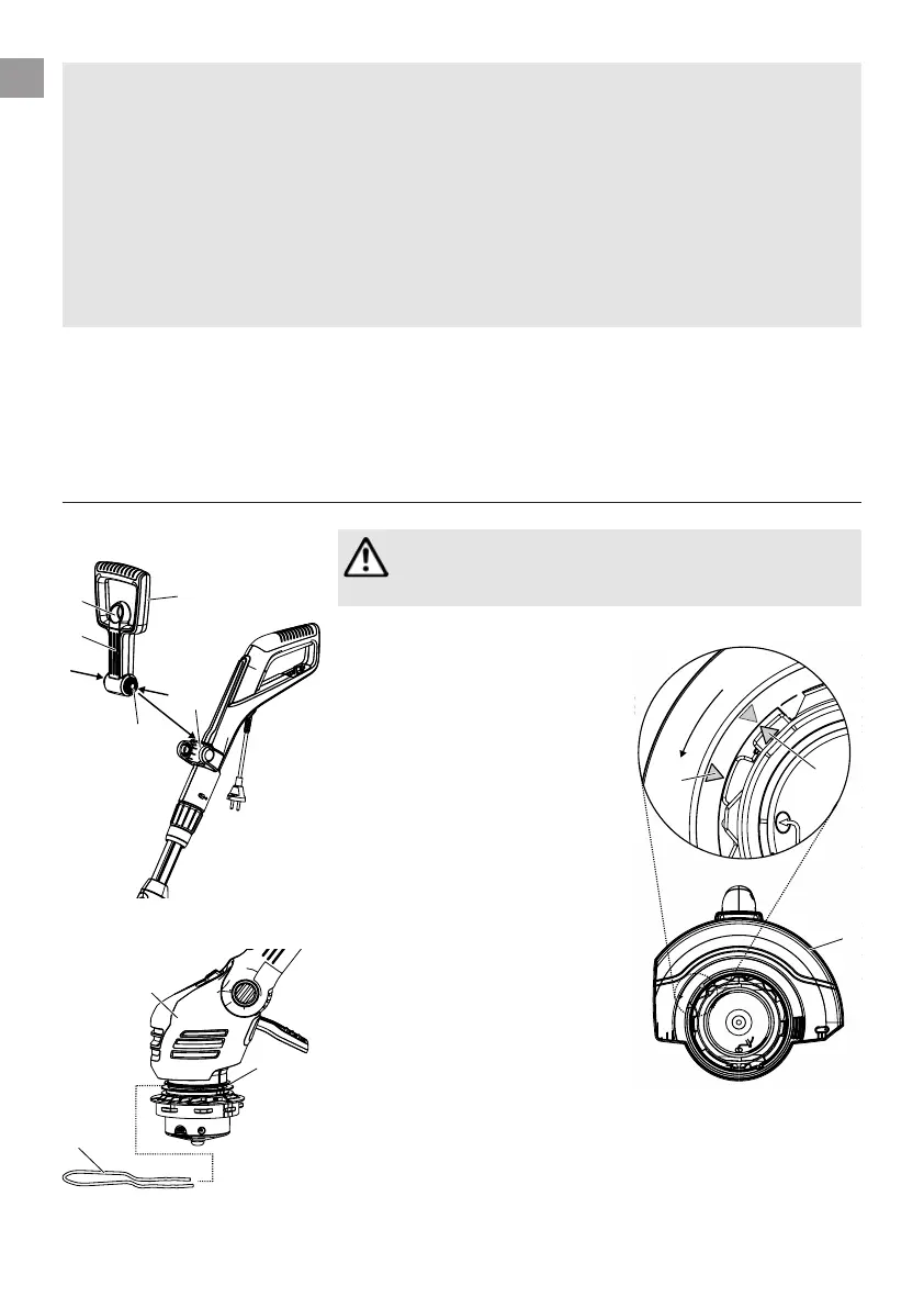
3. Assembly
Assembling the trimmer:
1
2
3
4
ß
R
7
9
CAUTION!
The trimmer may only be operated provided that the
protective cover
0
is assembled.
1. Pull the lock
1
belonging to the
additional handle
2
, push in both
of the snap-fits
3
belonging to
the additional handle
2
and, with
the grooves
ß
R
pointing forwards,
snap them into the holder
4
.
2. From the front, push the plant
guard
8
into the upper groove
9
of the trimmer head
7
.
In doing so, ensure that the
installed bow can rotate
freely (i. e. insert the bow with
the kink pointing upwards).
3. Place the protective cover
0
on
top of the trimmer head
7
.
4. Turn the protective cover
0
until it can be pushed over the
trimmer head entirely (the two
arrows
ß
A1
,
ß
A2
are directly across
from each other).
5. Rotate the protective cover
0
anti-clockwise until it audibly
engages.
0
A1
ß
ß
A2
Supply lines must be lighter than:
– common rubber lines (H 05 RNF),
if rubber-insulated;
– common PVC-coated lines (H 05 WF),
if insulated with PVC.
v Only connect the device to a mains circuit
which is equipped with a residual current
device (RCD) with a maximum release current
of 30 mA.
In Switzerland the use of a residual-current
device is obligatory.
Warning! This unit makes an electromagnetic
field while it operates. This field may under some
conditions interfere with active or passive medi-
cal implants. To decrease the risk of conditions
that can possibly injure or kill, we recommend
persons with medical implants to speak with
their physician and the medical implant manu-
facturer before operating.
Warning! Keep toddlers away when you assem-
ble the unit. Small parts can be easily swallowed.
There is also a risk that the polybag can suffocate
toddlers.
14
GB